Power Conversion Device
a power conversion device and power technology, applied in the direction of motor/generator/converter stopper, dynamo-electric converter control, starter details, etc., can solve the problems of power loss, increased heat generation, increased state, etc., to reduce the number of times of switching elements, increase reliability, and reduce the effect of switching elements
- Summary
- Abstract
- Description
- Claims
- Application Information
AI Technical Summary
Benefits of technology
Problems solved by technology
Method used
Image
Examples
first embodiment
The First Embodiment
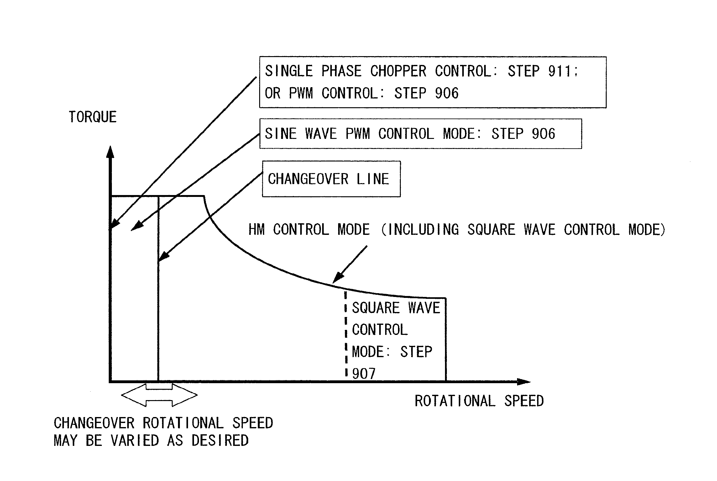
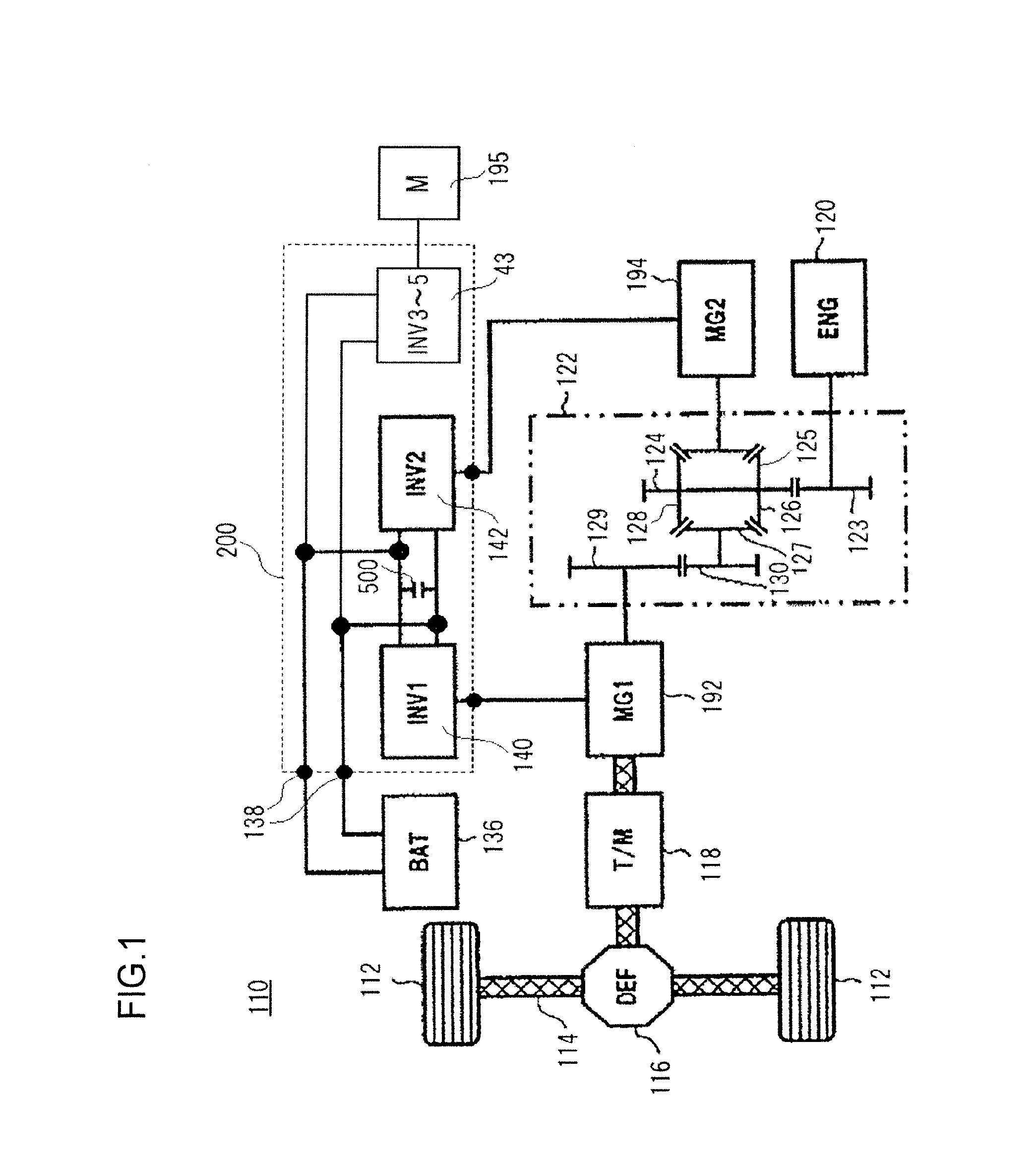
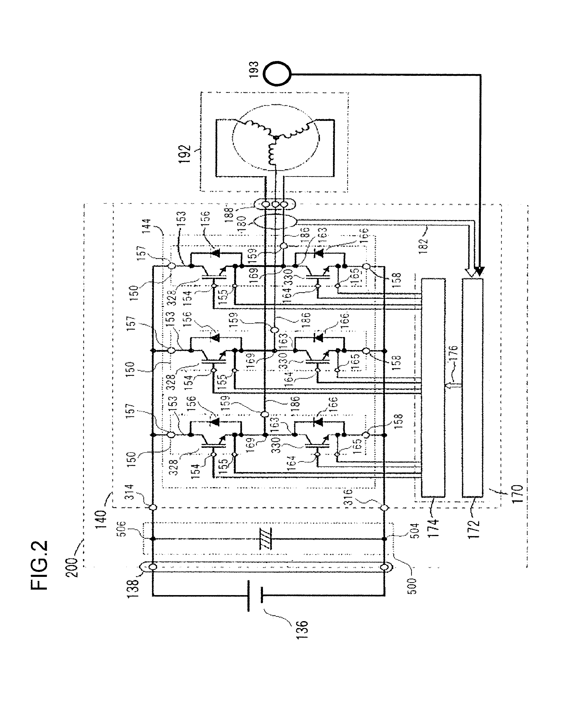
[0130]A block diagram in which the functions of the motor control system employing this control circuit 172 according to the first embodiment of the present invention are shown as functional blocks is given in FIG. 6. A control command for the motor-generator 192, for example a torque command T* that provides a target torque value, is inputted to the control circuit 172 by a higher level control device that controls the vehicle. Using data in a torque / rotational speed map that has been stored in advance, a torque command to current command converter 410 converts a torque command to a d axis current command signal Id* and a q axis current command signal Iq* on the basis of this torque command T* that has been inputted and rotational speed information according to a magnetic pole position signal θ detected by a magnetic pole rotation sensor 193. The d axis current command signal Id* and the q axis current command signal Iq* thus produced by the torque command to cu...
second embodiment
The Second Embodiment
[0223]A motor control system having a control circuit 172 according to a second embodiment of the present invention is shown in FIG. 31. As compared with the motor control system according to the first embodiment shown in FIG. 6, this motor control system is additionally provided with a transient current compensator 460.
[0224]This transient current compensator 460 generates a compensation current for compensating for a transient current created in the phase current flowing to the motor-generator 192 when the control mode is changed over from PWM control to HM control, or from HM control to PWM control. This generation of a compensation current is performed by detecting the phase voltage during the control mode changeover, and by outputting a modulated wave in pulse form from the transient current compensator 460 to the driver circuit 174, for generating a compensation pulse so as to cancel out the phase voltage that has been detected. The compensation pulse is g...
third embodiment
The Third Embodiment
[0238]A motor control system with a control circuit 172 according to a third embodiment of the present invention is shown in FIG. 37. As compared with the motor control system according to the second embodiment shown in FIG. 31, this motor control system further includes a current controller (ACR) 422, a chopper period generator 470, and a pulse modulator 480 for single phase chopper control.
[0239]In a similar manner to the current controllers (ACRs) 420 and 421, the current controller (ACR) 422 calculates a d axis voltage command signal Vd* and a q axis voltage command signal Vq* on the basis of the d axis current command signal Id* and the q axis current command signal Iq* that are outputted from the torque command to current command converter 410, and on the basis of the phase current detection signals lu, lv, and lw of the motor-generator 192 that are detected by the current sensor 180. And the d axis voltage command signal Vd* and the q axis voltage command ...
PUM
 Abstract
Description
Claims
Application Information
 - R&D
- Intellectual Property
- Life Sciences
- Materials
- Tech Scout
- Unparalleled Data Quality
- Higher Quality Content
- 60% Fewer Hallucinations
Browse by: Latest US Patents, China's latest patents, Technical Efficacy Thesaurus, Application Domain, Technology Topic, Popular Technical Reports.
© 2025 PatSnap. All rights reserved.Legal|Privacy policy|Modern Slavery Act Transparency Statement|Sitemap|About US| Contact US: help@patsnap.com


