Eureka AIR delivers breakthrough ideas for toughest innovation challenges, trusted by R&D personnel around the world.

Apparatus for cylindrical magnetron sputtering

a cylindrical magnetron and apparatus technology, applied in the direction of electrolysis components, vacuum evaporation coatings, coatings, etc., can solve the problems of difficult to simultaneously optimize target utilization and sputtering uniformity, and adverse effects not only on sputtering rate, so as to improve target utilization

Active Publication Date: 2014-02-27
CARDINAL CG
View PDF5 Cites 12 Cited by
  • Summary
  • Abstract
  • Description
  • Claims
  • Application Information

AI Technical Summary

Benefits of technology

The invention is about a cathode target assembly used for sputtering target material onto a substrate. It includes a cylindrical target that rotates and a magnetic array that remains static. The magnetic array is formed in a racetrack configuration with inner and outer magnetic poles. The target has a straight portion and opposing end portions that fan outwards. The orientation of the magnetic poles is parallel to each other in the first direction along the straight portion and then extends outwards in a second direction to form the end portions. One or more of the end portions are selectively adjustable in orientation relative to the target. The technical effect of the invention is to provide a more effective and precise method for sputtering target material onto a substrate.

Problems solved by technology

As the groove deepens, it tends to have an adverse effect not only on the sputtering rate, but also on the uniformity of the film deposition on the substrate.
Although the use of cylindrical magnetron targets has resulted in improved target utilization, it has been difficult to simultaneously optimize target utilization and sputtering uniformity.

Method used


Image

  • Apparatus for cylindrical magnetron sputtering
  • Apparatus for cylindrical magnetron sputtering
  • Apparatus for cylindrical magnetron sputtering

Examples


Embodiment Construction

[0034]The following detailed description should be read with reference to the drawings, in which like elements in different drawings are numbered identically. The drawings depict selected embodiments and are not intended to limit the scope of the invention. It will be understood that embodiments shown in the drawings and described below are merely for illustrative purposes, and are not intended to limit the scope of the invention as defined in the claims.

[0035]Cylindrical Magnetron Target Assemblies and Exemplary Substrates

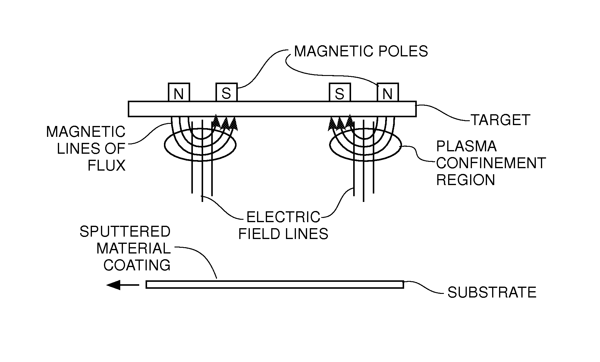
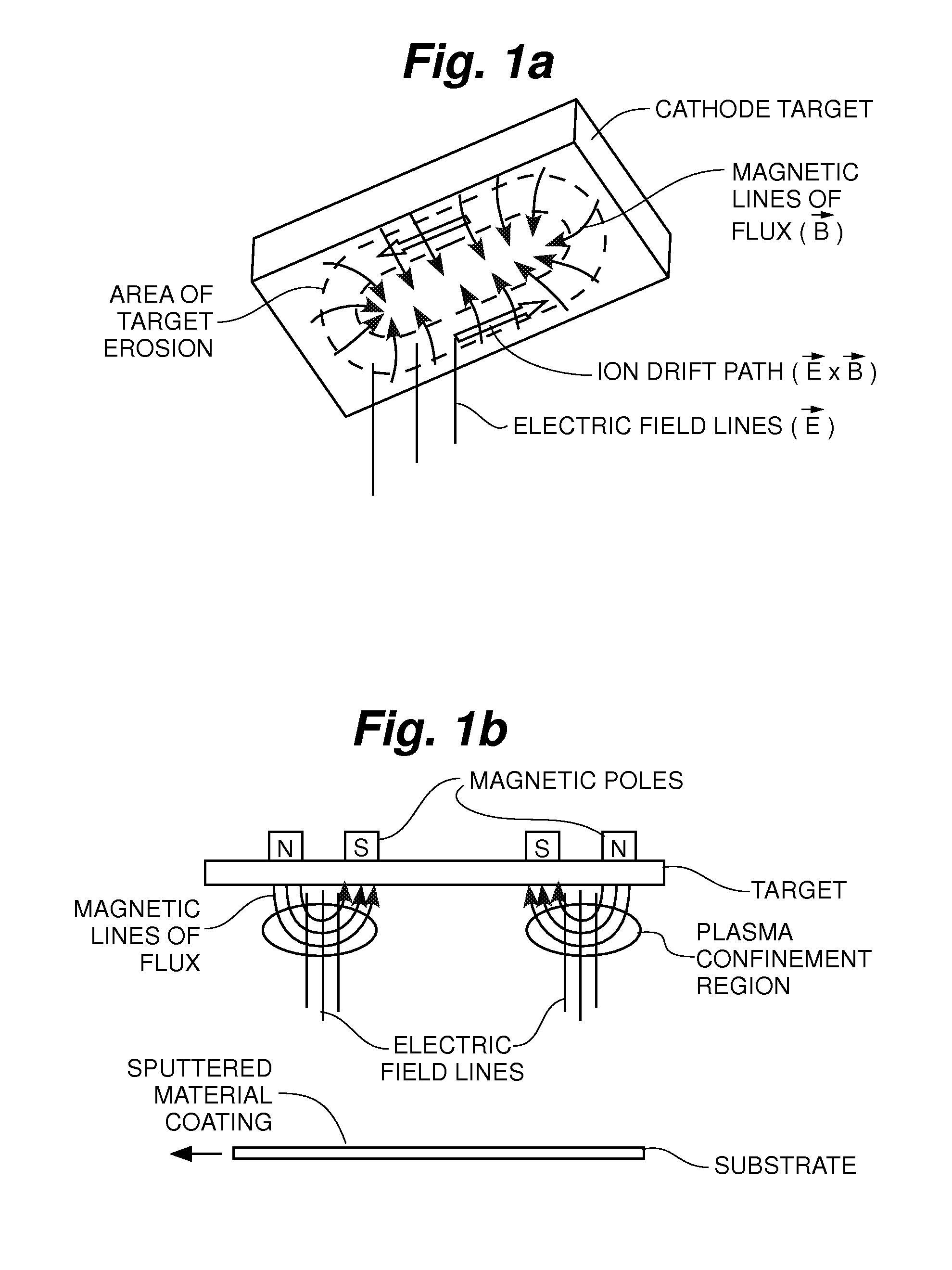
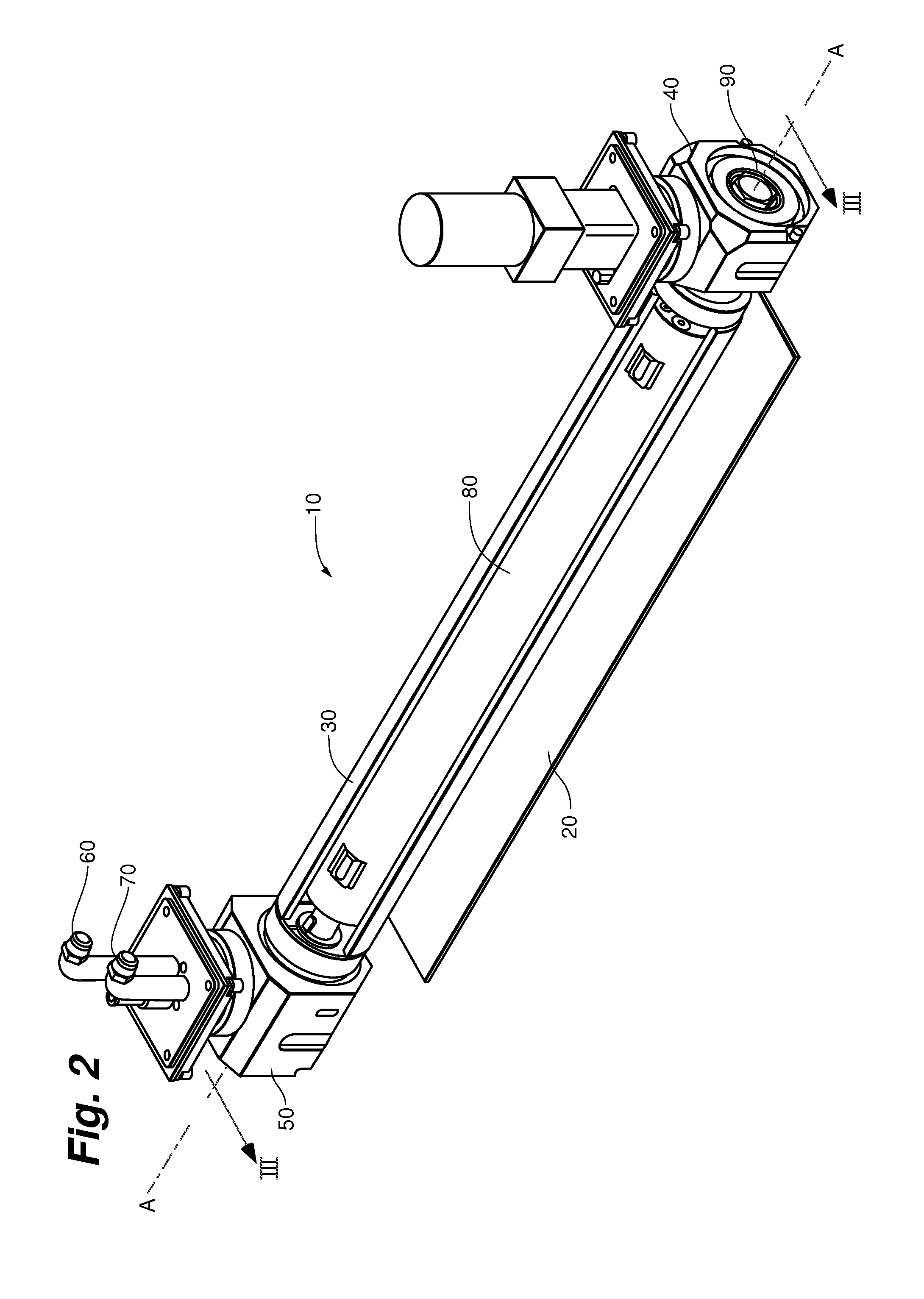
[0036]As already described, one drawback to using planar magnetron targets for sputtering applications has been poor optimization of the target material. By using cylindrical magnetron targets as an alternative, target optimization has been greatly increased. Such increased optimization is generally achieved by keeping the magnet assembly stationary while rotating the cylindrical target about it. Such a cylindrical magnetron target, along with its corresponding as...


PUM

PropertyMeasurementUnit
Angleaaaaaaaaaa
Strengthaaaaaaaaaa
Magnetismaaaaaaaaaa

Abstract

A cathode target assembly for use in sputtering target material onto a substrate includes a generally cylindrical target and a magnetic array. The magnetic array is adapted to provide a plasma confinement region adjacent an outer surface of the target. End portions of the magnetic array are adapted to make the shape and strength of the confinement field at the turns of the racetrack closely match the shape and strength of the confinement field along the straight part of the racetrack so as to significantly reduce cross-corner effect.

Description

CROSS-REFERENCE TO RELATED APPLICATION[0001]This patent application claims priority to provisional U.S. Patent Application No. 61 / 693,032, filed on Aug. 24, 2012, the entire contents of which are hereby incorporated by reference herein.FIELD OF THE INVENTION[0002]The invention relates to apparatus for depositing films on surfaces, and more particularly to configurations of such apparatus for improving target utilization and deposition uniformity during magnetron sputtering operations.BACKGROUND[0003]A variety of methods exist to apply coatings, such as thin films, to substrates, such as glass. Generally, sputtering is a technique for forming a thin film on a substrate. Sputtering techniques include diode sputtering, triode sputtering, and magnetron sputtering.[0004]Magnetron sputtering has become a widely-used sputtering technique. Films formed by sputtering can be important for numerous devices, such as semiconductors and window glass. Films, created by these processes, are typical...

Claims


Application Information

Patent Timeline
IPC IPC(8): C23C14/35
CPCC23C14/35C23C14/3407C23C14/352C23C14/562H01J37/3405H01J37/3452H01J37/347H01J2237/334
Inventor GERMAN, JOHN R.HARTIG, KLAUS H.W.
Owner CARDINAL CG
Why Eureka
Eureka Blog
Learn More