

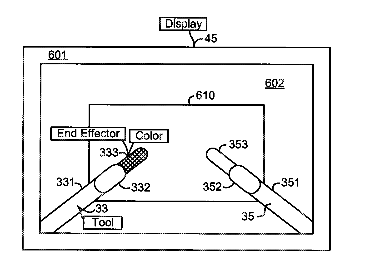
Rendering tool information as graphic overlays on displayed images of tools
a tool information and graphic overlay technology, applied in the field of robotic systems, can solve problems such as difficult to readily see, objectionable obstructing the image of tools and/or objects, and difficult to understand the information of tools
- Summary
- Abstract
- Description
- Claims
- Application Information
AI Technical Summary
Benefits of technology
Problems solved by technology
Method used
Image

Examples
Embodiment Construction
[0019]Although a medical robotic system is described herein, it is to be appreciated that the various aspects of the invention are not to be limited to medical robotic systems. They are applicable to robotic systems in general.
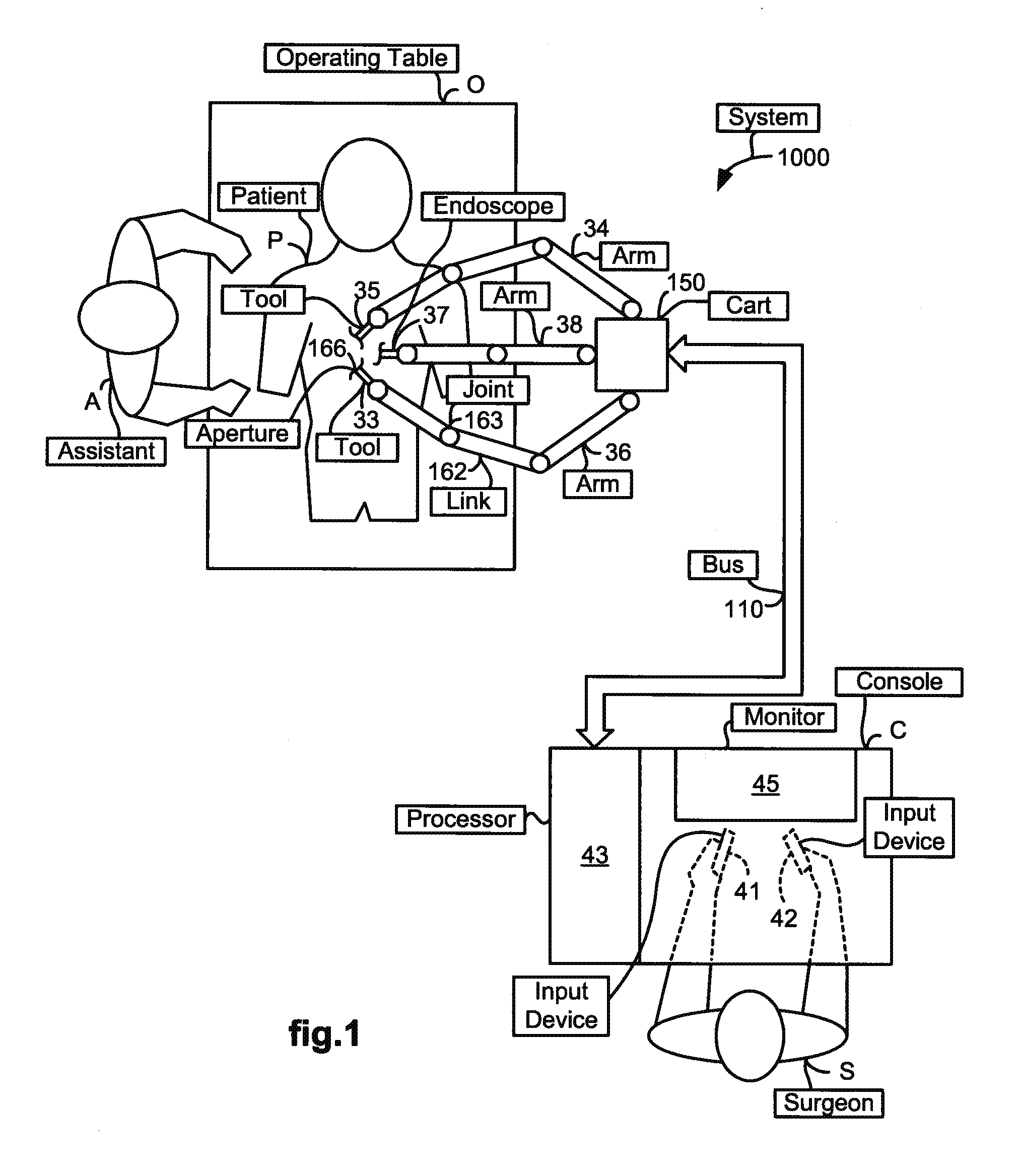
[0020]FIG. 1 illustrates a top view of an operating room in which a medical robotic system 1000 is being employed by a Surgeon (“S”) to perform a medical procedure on a Patient (“P”). The medical robotic system in this case is a Minimally Invasive Robotic Surgical (MIRS) system including a Console (“C”) utilized by the Surgeon while performing a minimally invasive diagnostic or surgical procedure on the Patient with assistance from one or more Assistants (“A”) while the Patient is on an Operating table (“O”).
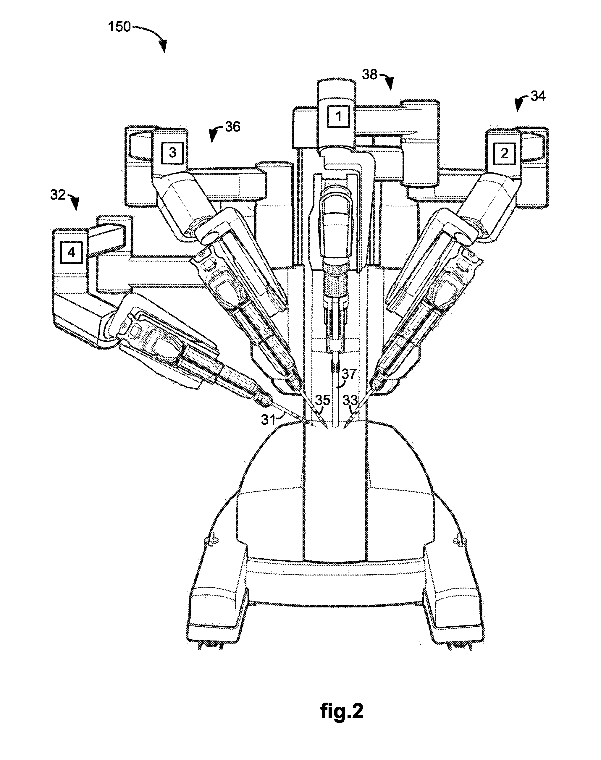
[0021]The Console, as further described in reference to FIG. 4, includes a processor 43 which communicates with a movable cart 150 over a bus 110. A plurality of robotic arms 34, 36, 38 are included on the cart 150. A tool 33 is held and manipulated by rob...
PUM
 Abstract
Description
Claims
Application Information