Eureka AIR delivers breakthrough ideas for toughest innovation challenges, trusted by R&D personnel around the world.

In-vehicle control device and in-vehicle recording system

a technology of in-vehicle control and recording system, which is applied in the direction of external condition input parameters, instruments, transportation and packaging, etc., can solve problems such as difficulty in taking preference or thinking, unplanned or unplanned behavior, and occupants may distrust the control of the driving assist devi

Active Publication Date: 2017-05-25
TOYOTA JIDOSHA KK
View PDF0 Cites 20 Cited by
  • Summary
  • Abstract
  • Description
  • Claims
  • Application Information

AI Technical Summary

Benefits of technology

The patent describes a system for collecting and analyzing data from a vehicle to better understand the actions and changes in state of the occupants. The system uses two recording regions to capture data from different parts of the vehicle. By associating the data from the first recording region with data from the second recording region and analyzing it in relation to the time of occurrence of an event, the system can better understand the actions of the occupant after an event. This reduces the data storage requirements on the second recording region and allows for a more complete analysis of the occupant's actions.

Problems solved by technology

In some cases, control on the vehicle by the driving assist device may cause a behavior that is unexpected or unforeseen for a driver or a passenger (hereinafter, an occupant).
One of the factors that can cause such a situation is a difficulty in taking preference or way of thinking of all the occupants into consideration in development of the driving assist device.
When the behavior that is unexpected or unforeseen for an occupant is caused by control on the vehicle by the driving assist device, the occupant may distrust the control by the driving assist device.
However, the driving assist device in the related art was unable to acquire the data indicating what kind of operation the occupant performed or the data indicating how the state of the occupant was changed as a result of occurrence of an event such as a control on the vehicle by the driving-assist.
The driving assist device in the related art was also unable to acquire the data indicating what kind of operation the occupant performed or the data indicating how the state of the occupant was changed when an event of the level not triggering the driving assist (such as a quick brake and a steep turn) occurred.
Such circumstances might deprive developers and designers of an opportunity to design a system that performs vehicle control without interfering with an intention of operation by the occupant.

Method used


Image

  • In-vehicle control device and in-vehicle recording system
  • In-vehicle control device and in-vehicle recording system
  • In-vehicle control device and in-vehicle recording system

Examples


first embodiment

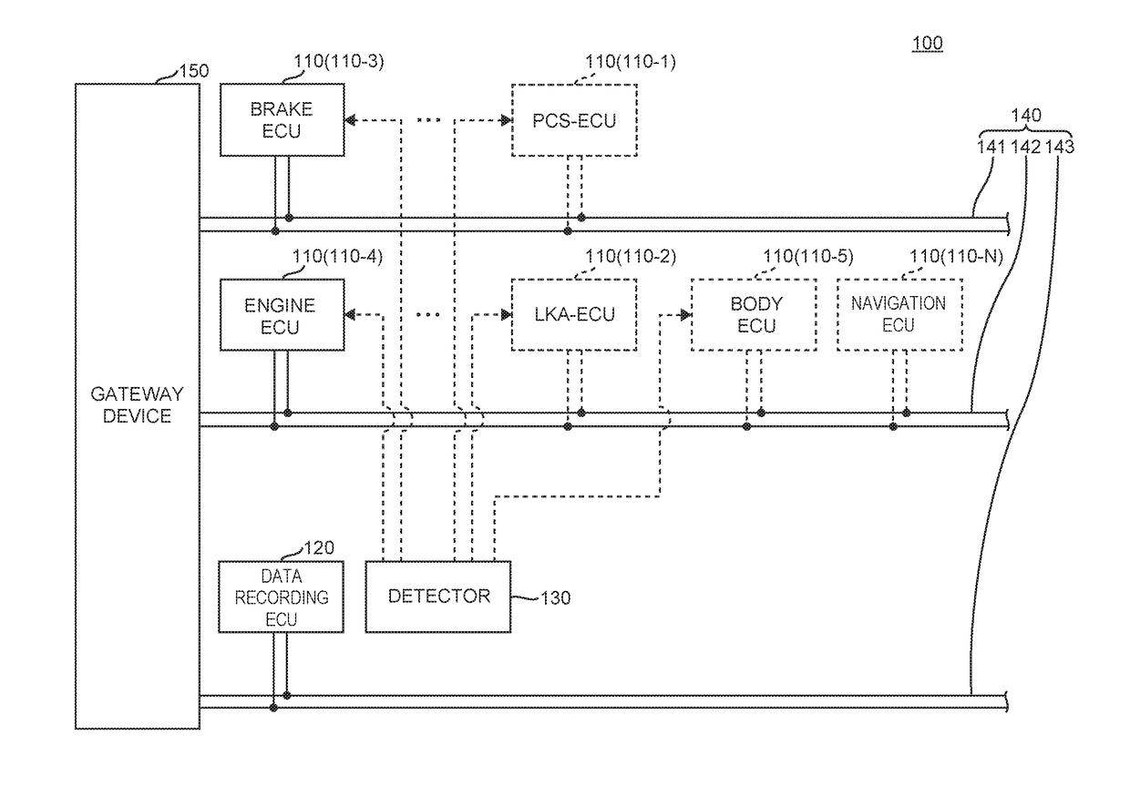
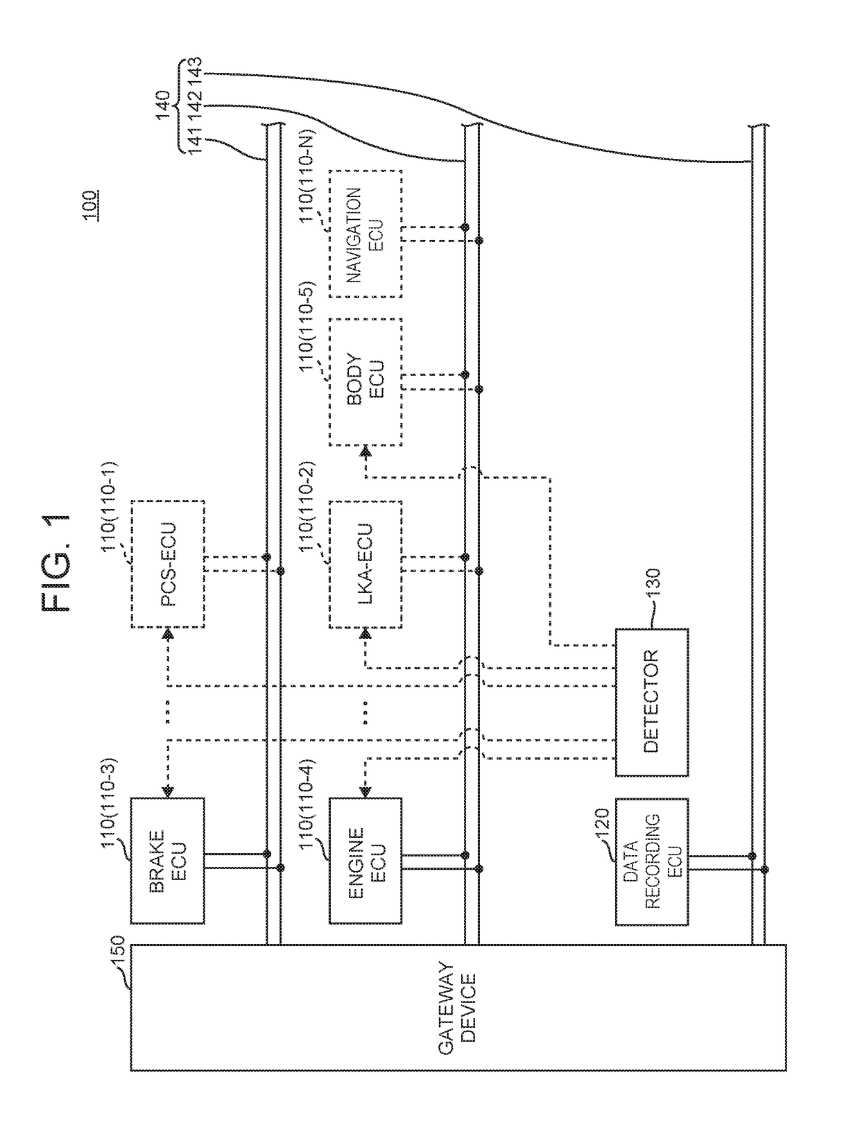
[0057]FIG. 1 illustrates one example of the configuration of the in-vehicle recording system 100 in the first embodiment.

[0058]The in-vehicle recording system 100 includes ECUs 110 (a pre-crash safety (PCS)-electronic control unit (ECU) 110-1, a lane keeping assist (LKA)-ECU 110-2, a brake ECU 110-3, an engine ECU 110-4, a body ECU 110-5 . . . and a navigation ECU 110-N), a data recording ECU 120, a detector 130, a controller area network (CAN) 140, and a gateway device 150.

[0059]The in-vehicle recording system 100, which is mounted in a vehicle, records status data prescribed for each type of the event, when the event of any prescribed type is detected. Hereinafter, a term “vehicle” refers to the vehicle that incorporates the in-vehicle recording system 100 unless otherwise specified.

[0060]A term “event” refers to, for example, the phenomenon that occurs in a vehicle that is controlled based on such parameters as control values calculated for vehicle control or control signals gene...

second embodiment

[0370]An in-vehicle control device and an in-vehicle recording system of the second embodiment are different from the first embodiment in the point that the data recorded on the first recording region of the data recording unit 127 (the event ID, the status data before and after occurrence of an event, and the cumulative number of times of startup and time stamp data at the time of occurrence of the event) is not associated with the data recorded on the second recording region of the data recording unit 127 (the subsequent change data representing a subsequent change occurring after occurrence of the event, and the cumulative number of times of startup and time stamp data).

[0371]Since the second embodiment is similar in other aspects to the in-vehicle control device (data recording ECU 120) and the in-vehicle recording system 100 of the first embodiment, a description is mainly given of the difference from the first embodiment. In the description below, some of the drawings of the f...

third embodiment

[0381]An in-vehicle control device and an in-vehicle recording system of the third embodiment are different from those of the first embodiment, in the point that the data recorded on the first recording region of the data recording unit 127 is associated with the data recorded on the second recording region of the data recording unit 127 while the cumulative number of times of startup and the time stamp is not associated with the subsequent change data.

[0382]Since the third embodiment is similar in other aspects to the in-vehicle control device (data recording ECU 120) and the in-vehicle recording system 100 of the first embodiment, a description is mainly given of the difference from the first embodiment. In the description below, some of the drawings of the first embodiment will be used.

[0383]In the third embodiment, the data acquisition unit 124A acquires the cumulative number of times of startup and time stamp data at the time of occurrence of an event, and records the data on t...


PUM


Abstract

An in-vehicle control device includes a recording unit that sequentially records first data transferred through an in-vehicle local network; a data acquisition unit that acquires second data relating to an event from a portion of the first data generated within a first time before occurrence of the event and from another portion of the first data recorded within a second time after occurrence of the event; a generation unit that generates third data when a specified operation or change in state of an occupant occurs by elapse of a third time after occurrence of the event; a first holding unit that holds the second data; a second holding unit that holds the third data; a nonvolatile memory having a first and a second recording regions; and a data control unit that records the second data on the first recording region and the third data on the second recording region.

Description

INCORPORATION BY REFERENCE[0001]The disclosure of Japanese Patent Application No. 2015-228007 filed on Nov. 20, 2015 including the specification, drawings and abstract is incorporated herein by reference in its entirety.BACKGROUND[0002]1. Technical Field[0003]The present disclosure relates to an in-vehicle control device and an in-vehicle recording system.[0004]2. Description of the Related Art[0005]There is a driving assist device that collects surrounding information on an own vehicle by an in-vehicle sensor, determines a danger degree at the time of traveling based on the collected information corresponding to actual road conditions, and controls the vehicle based on the determined danger degree (see, for example, Japanese Patent Application Publication No. 2014-211756).[0006]In some cases, control on the vehicle by the driving assist device may cause a behavior that is unexpected or unforeseen for a driver or a passenger (hereinafter, an occupant). One of the factors that can ca...

Claims


Application Information

Patent Timeline
IPC IPC(8): G07C5/08B60W50/08
CPCB60W50/08G07C5/0841B60R16/0231B60W50/14G07C5/085B60R16/023G07C5/00G07C5/008B60W2050/143B60W2050/146B60W2554/00
Inventor IWAASA, SHINTARO
Owner TOYOTA JIDOSHA KK
Why Eureka
Eureka Blog
Learn More