

Method for pressure-sensor wear state determination of a valve mechanism
a technology of wear state determination and valve mechanism, which is applied in the direction of digital computer details, instruments, nuclear elements, etc., can solve the problems of reducing the movement speed of the valve element, affecting the operation of the entire installation or vehicle, and increasing static friction and sliding friction of the valve mechanism
- Summary
- Abstract
- Description
- Claims
- Application Information
AI Technical Summary
Benefits of technology
Problems solved by technology
Method used
Image

Examples
Embodiment Construction
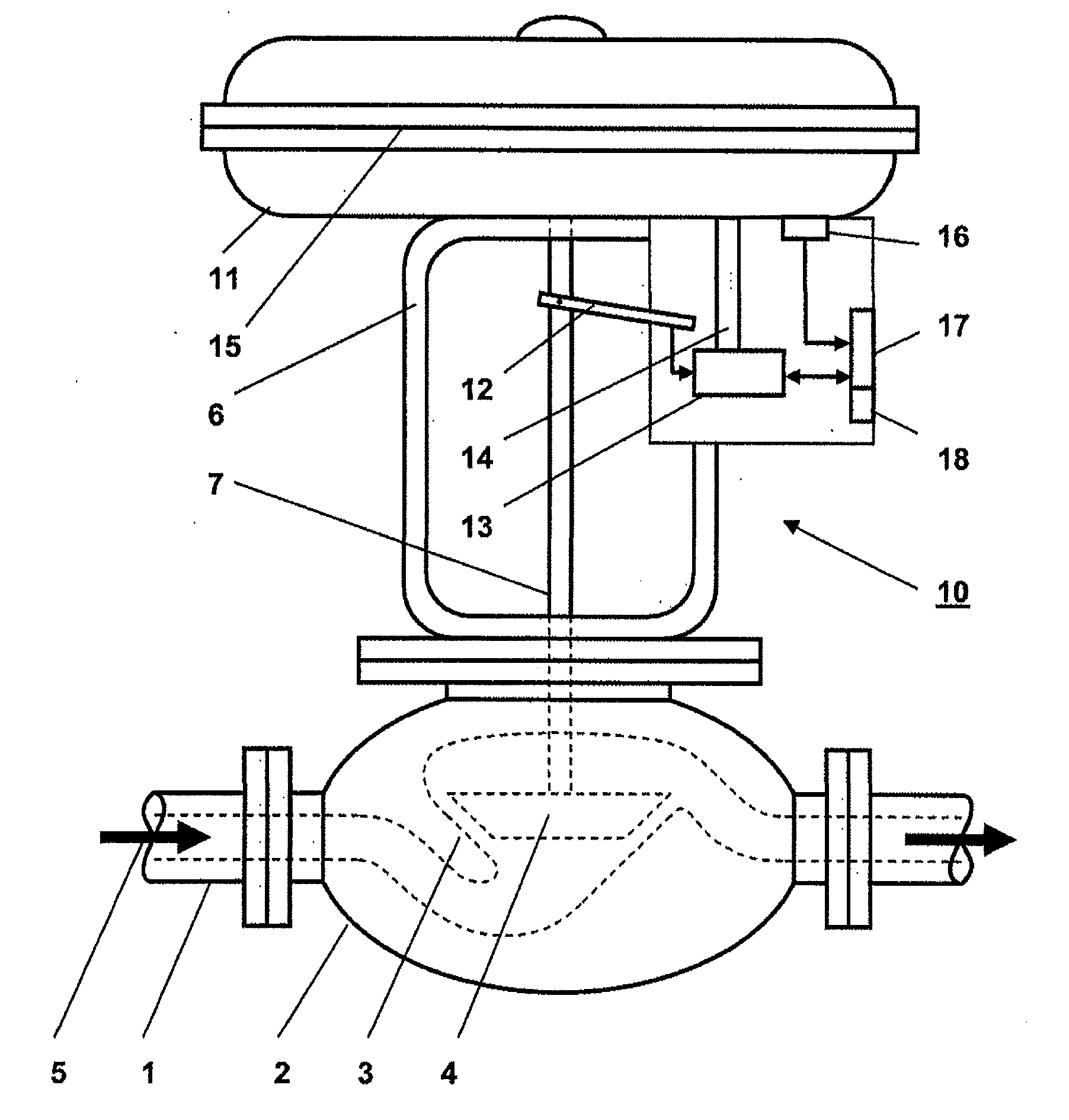
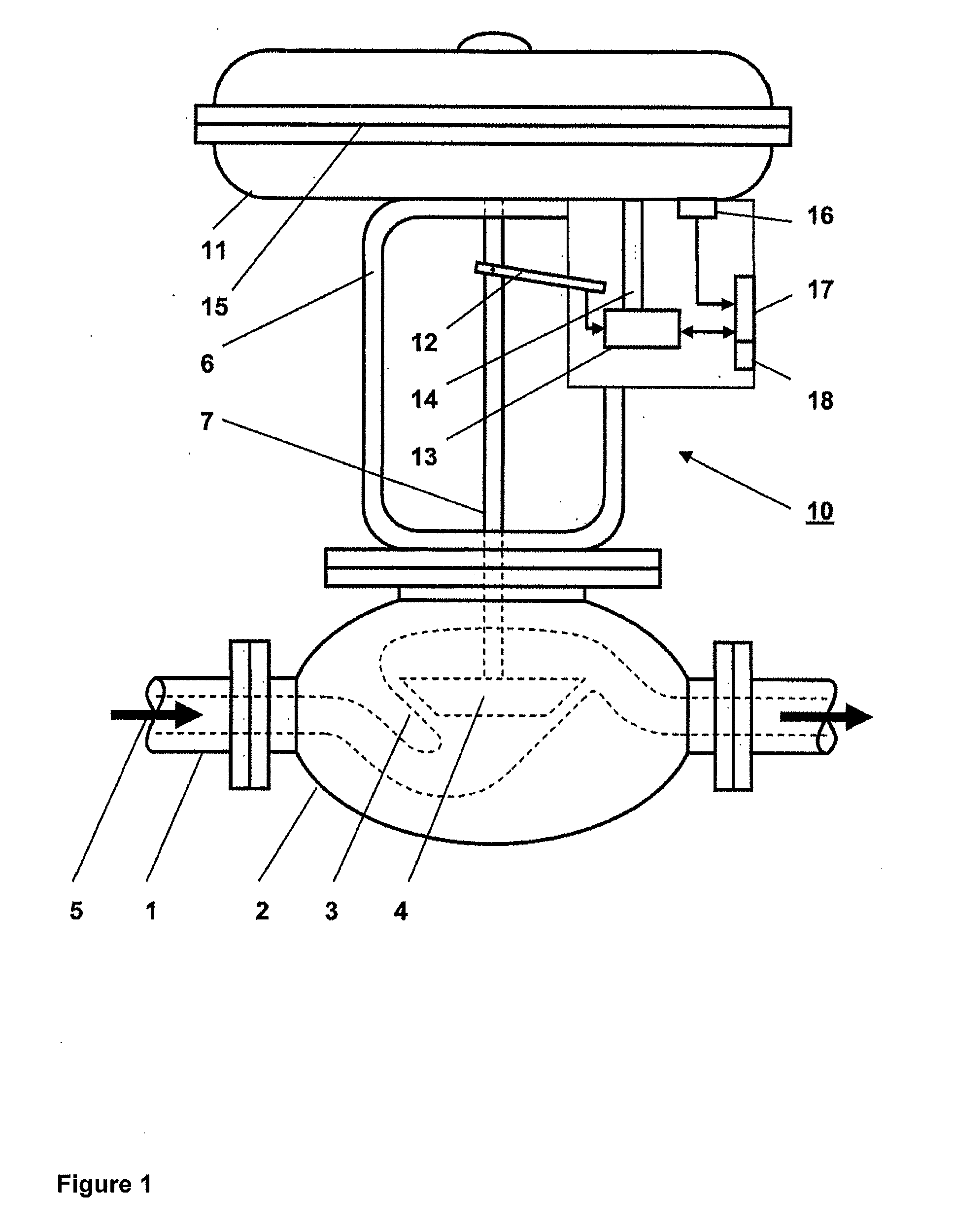
[0018]A method is disclosed for pressure-sensor operating state determination of a valve mechanism of a pneumatic actuating drive, for example, to ensure correct determination of static friction of a valve element as an operating state indicator.
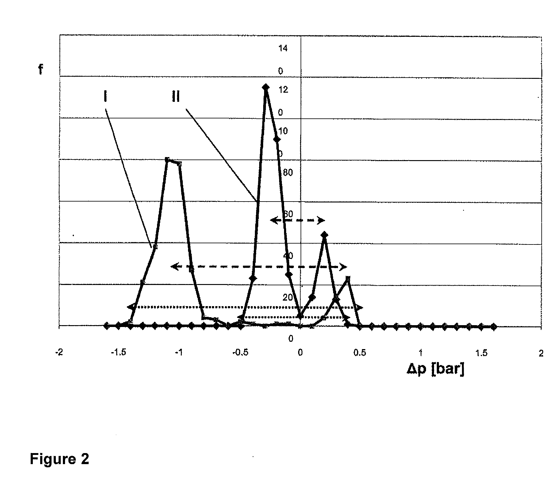
[0019]The disclosure includes the technical teaching that the pressure rise value Δp of the control pressure required to start movement of the valve element can be measured repeatedly and successively after movement of the valve element has been stopped, after which the measured pressure rise values can be temporarily stored in a memory unit, which a diagnosis unit accesses to determine the probable influence of the static friction on movement of the valve element, by statistical analysis.
[0020]Since the influence of the static friction during movement of the valve element can be a more random event, this can be determined and eliminated by static mathematical analyses. With this static analysis, noise-dependent measurement areas can be effe...
PUM
 Abstract
Description
Claims
Application Information