Supercharge Your Innovation With Domain-Expert AI Agents!

Optical module and scan-type image projection display device

a technology of optical modules and display devices, applied in the field of optical modules and scan-type image projection display devices, can solve the problems reducing the luminous efficacy, and reducing the luminous efficiency of laser outputs, etc., and achieve the effect of reducing the relative beam spot displacemen

Active Publication Date: 2014-02-27
HITACHI-LG DATA STORAGE
View PDF4 Cites 6 Cited by
  • Summary
  • Abstract
  • Description
  • Claims
  • Application Information

AI Technical Summary

Benefits of technology

The present invention is related to an optical module for image projection display devices. The present invention aims to reduce the displacement of laser beams in the display area (screen) and provide a scan-type image projection display device that can effectively display images. The technical effects of the present invention can be used in head-up displays installed in cars. The optical module has a small size and is capable of reducing the relative beam spot displacement in the display area, improving the clarity and accuracy of the projected images.

Problems solved by technology

Further, if the temperature of the laser diodes rises extremely due to a temperature rise of the scan-type image projection display device in use and exceeds the operation guarantee temperature of the laser diodes, the temperature-dependent laser wavelength variations cause a difference in the luminous efficacy (luminosity factor) among the colors and that results in color shifts in the displayed image (e.g. reddish colors throughout the image).
The high temperature also causes a drop in the laser outputs and a decrease in the operating life of the laser diodes.
However, the attaching method of the JP-2011-150742-A has not paid attention to the positions of attachment suitable for preventing the shift and rotation of the optical axes of the optical components even though the shift and rotation of the optical components' optical axes are essential problems with the optical module to be considered.

Method used


Image

  • Optical module and scan-type image projection display device
  • Optical module and scan-type image projection display device
  • Optical module and scan-type image projection display device

Examples


first embodiment

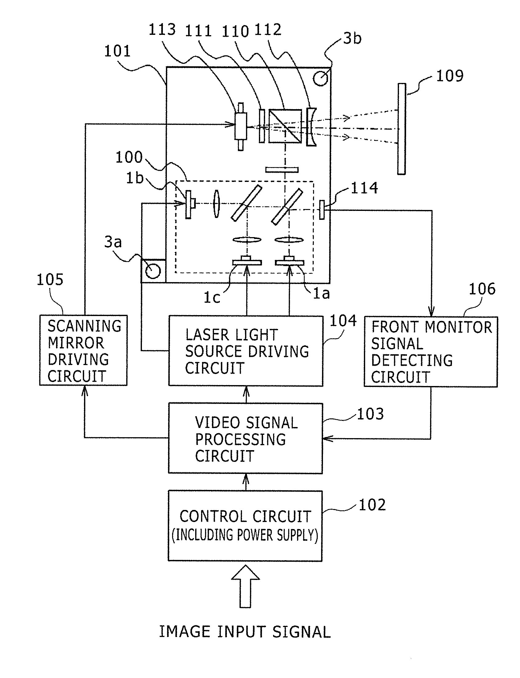
[0034]FIG. 1 is a block diagram showing the configuration of a scan-type image projection display device according to a first embodiment of the present invention.

[0035]In FIG. 1, an optical module 101 of the scan-type image projection display device includes a laser light source module 100, a projection unit, and a scanning unit. The laser light source module 100 includes a first laser 1a, a second laser 1b and a third laser 1c serving as laser light sources corresponding to three colors (red (R), green (G), blue (B)) and a beam coupling unit for coupling the optical beams (laser beams) emitted from the laser light sources. The projection unit projects the coupled optical beam onto a screen 109. The scanning unit executes two-dimensional scanning of the projected optical beam on the screen 109. The projection unit includes a polarization beam splitter (PBS) 110, a quarter wave plate 111, a view angle enlarging element 112, etc. The scanning unit includes a scanning mirror 113, etc. ...

second embodiment

[0053]FIG. 3 is a block diagram showing the configuration of a scan-type image projection display device according to a second embodiment of the present invention.

[0054]The second embodiment differs from the first embodiment in that the scanning mirror 113 (employed in the first embodiment) is configured in the second embodiment to project the image from its back side to its front side as shown in FIG. 3.

[0055]Therefore, the first laser 1a, the second laser 1b, the third laser 1c, the first attachment part 3a and the second attachment part 3b are arranged symmetrically to those in FIG. 1 in regard to the horizontal direction and the image is projected from the back to the front of the scanning mirror 113 via a reflecting mirror 115 which is used instead of the polarization beam splitter 110. The other configuration of the scan-type image projection display device is basically equivalent to that in the first embodiment.

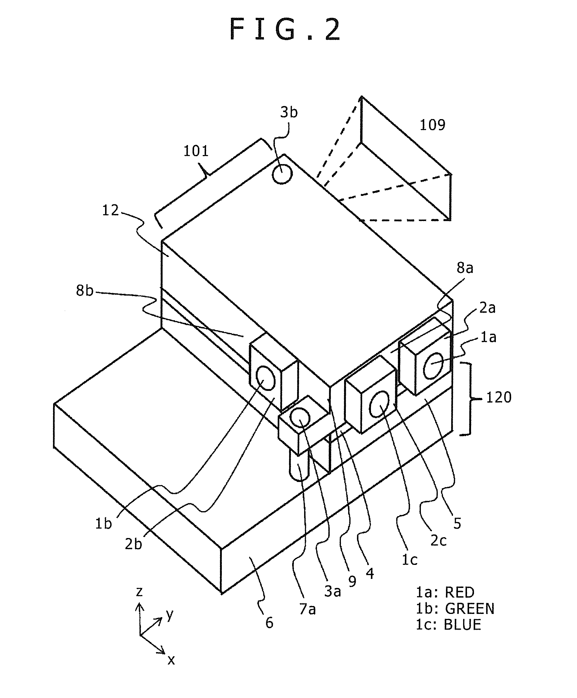
[0056]FIG. 4 is a perspective view for explaining the optical mod...

third embodiment

[0059]FIG. 5 is a perspective view showing a third embodiment of the present invention regarding the attachment part of the case.

[0060]In order to relax the torque at the time of the attachment (e.g. screwing) of the first attachment part 3a, a slit part 13a is formed in the structure around the case 12 so as to make the slit part 13a deform and absorb the screwing torque, etc. at the time of the attachment.

[0061]By forming the slit part 13a, the deformation of the case 12 due to the screwing torque, etc. can be suppressed and the displacement / rotation of the optical components can be avoided, implementing an optical module 101 free from the optical axis shift of the laser beam of each color, that is, the relative beam spot displacement in the display area (e.g., screen).

[0062]While the slit part 13a has two slits formed on both sides of the first attachment part 3a in the example of FIG. 5, a similar effect of suppressing the deformation of the case 12 can be achieved even if one s...


PUM


Abstract

An optical module including a plurality of laser diodes and outputting optical beams emitted from the laser diodes includes a radiator unit for radiating heat and a case enclosing the optical module. The case has a first attachment surface to which a red laser diode is attached, a second attachment surface to which a green laser diode is attached, and a corner part where the first and second attachment surfaces intersect with each other. The optical module has a first attachment part, for connecting the case to the radiator unit, in the vicinity of the corner part.

Description

BACKGROUND OF THE INVENTION[0001]1. Field of the Invention[0002]The present invention relates to an optical module and a scan-type image projection display device. In particular, the present invention relates to, for example, an optical module for coupling optical beams emitted from a plurality of laser diodes into a beam on one optical axis and outputting the coupled optical beam, and a scan-type image projection display device for displaying images by use of the optical beam from the optical module.[0003]2. Description of the Related Art[0004]Small-sized projectors, easily portable and capable of displaying images in large screen sizes, are being developed actively in recent years. Small-sized projectors connectable to notebook PCs, video cameras equipped with a built-in projector capable of projecting recorded images, etc. are already available commercially. Cellular phones and smartphones equipped with a built-in projector are also expected to appear in the near future.[0005]As ...

Claims


Application Information

Patent Timeline
IPC IPC(8): H04N5/74F21V29/00
CPCF21V29/20H04N5/7408H04N9/3129H04N9/3173G02B26/101G03B21/16H04N9/3144G02B27/01
Inventor KATO, SEIICHIKAMESAWA, MASAHIKOTANAKA, TEPPEIMAKI, NOBUYUKI
Owner HITACHI-LG DATA STORAGE
Features
  • R&D
  • Intellectual Property
  • Life Sciences
  • Materials
  • Tech Scout
  • Unparalleled Data Quality
  • Higher Quality Content
  • 60% Fewer Hallucinations
Learn More