
Imaging calibration device

Inactive Publication Date: 2014-02-27
MATERIALISE NV
View PDF17 Cites 20 Cited by
  • Summary
  • Abstract
  • Description
  • Claims
  • Application Information

AI Technical Summary

Benefits of technology

The calibration devices in this patent can correct the geometry and greyscale values of images, such as medical images. This improves the quality of the image. The devices can also correct local inhomogeneities, which can enhance the quality of medical images. Many calibration devices have a housing that helps position them on the object of interest, such as a human body part. The housing may also have a patient-specific engagement surface.

Problems solved by technology

First of all, the geometrical accuracy is a common issue in dimensional metrology.
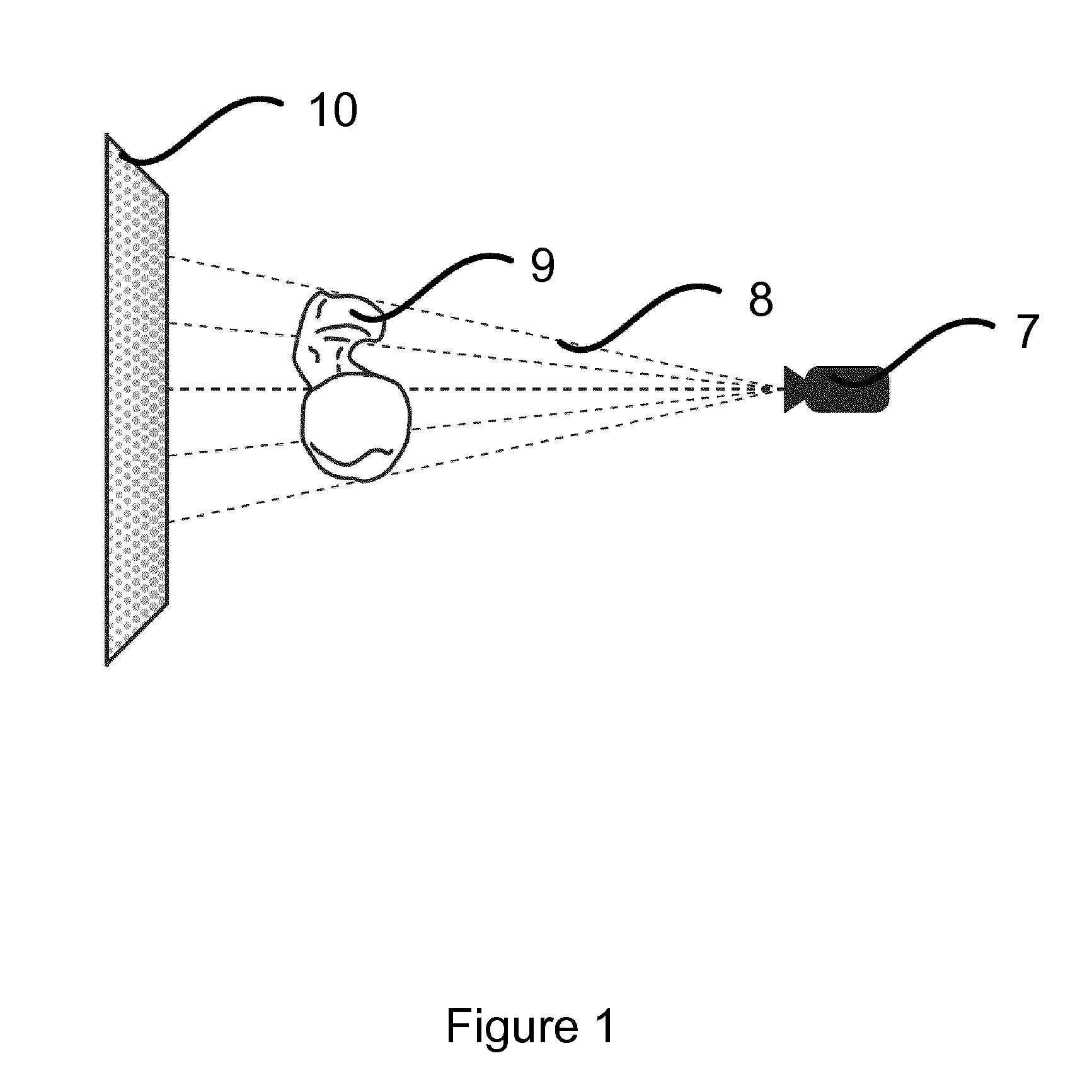
However, due to various mechanical and optical effects, radiographic images such as x-ray images can be distorted.
The result is that a certain distance on the image does not give an accurate estimate of the real distance, e.g. dimensions of certain anatomical parts.
Thus, uncalibrated x-ray images only offer qualitative information, not quantitative information.
A second issue is the grey-value accuracy of radiographic images.
As a result of the limited accuracy, it is for example hard to make a distinction between a five percent increase or decrease in size of a tumor, when comparing two x-ray images of the same body part taken at different times. On the other hand, when measuring osteoporosis, one can find a bone density based on the grey-values in a certain area of the image, but it is impossible to compare the grey-levels in this image to the levels in an image taken at a later time.
In practice, this is so cumbersome that it is rarely done.
Although these inventions can be used for determination of the magnification or minification of an image, they do not allow a more rigorous correction of the geometric distortions in the image, and the high radiopacity of the markers does not allow a grey-value correction.
Moreover, although these devices offer a high degree of freedom for positioning the marker relative to the body, they do not provide a means to do this in a reproducible way.
Additionally, these techniques only provide reference markers in one area of the image.
However, this system requires special and expensive equipment, and further requires obtaining a plurality of images of the region of interest.
Moreover, the system only allows geometrical calibration, not grey-value correction.

Method used


Image

  • Imaging calibration device
  • Imaging calibration device
  • Imaging calibration device

Examples


example 1

Development and Use of the Calibration Device

a) Development of the Calibration Device

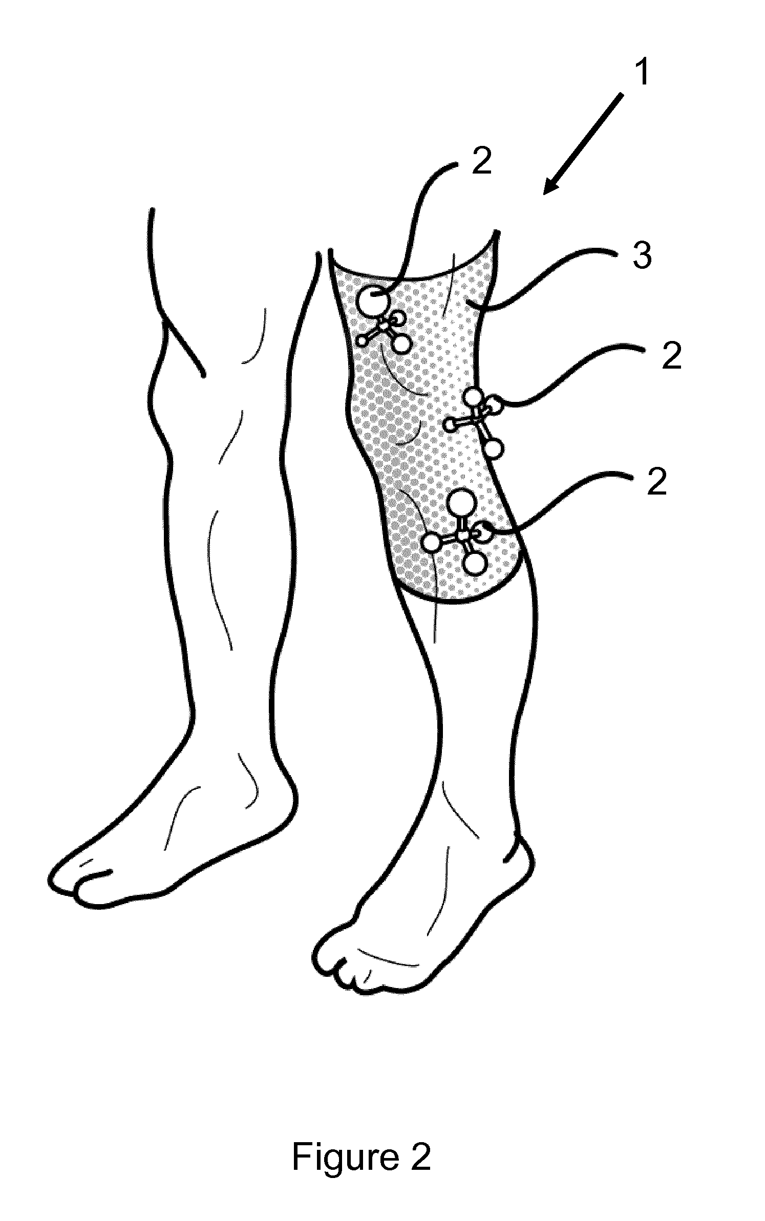
[0195]The calibration device (1) comprises several sets (2) of calibration components, as shown in FIG. 2.

[0196]An example of a set (2) according to a particular embodiment of the present invention is shown in FIG. 3. The set (2) consists of five calibration components (4, 5), which may be solid spheres with varying diameters, and / or hollow spheres with varying ratios between the large and the small radius (not shown). The varying diameters and / or ratios facilitate identification of the spheres. Moreover, the difference in overall diameter and / or thickness of the shell ensures differences in absorption rate between the spheres. The outer calibration components (4) are interconnected such that the lines connecting their centers form the edges of a tetrahedron, with one calibration component (5) in the center. Thus, there are four outer calibration components (4) and one inner calibration component (5...

example 2

Particular Embodiments of Interconnected Calibration Components

[0207]FIG. 6 (A-G) shows a set (2) of interconnected calibration components (4, 5) according to a particular embodiment of the present invention. The set comprises one spherical calibration component (4) connected to three calibration components (4′), each consisting of a solid cylindrical rod and a sphere. The rods form the edges of a tetrahedron, whereas the spheres form the vertices of the tetrahedron. The combination of the spheres and rods allows for a full 3D geometric and grey-value correction of a medical image such as a radiographic image. The spheres are identical, but can be identified in an x-ray image because each of the rods of the calibration components has a unique width.

[0208]The relative position of the spheres is fixed via the rods and further secured via a housing (11) holding the spheres. The housing also encapsulates the spheres, thereby protecting their structural integrity. The housing consists of...

example 3

Particular Embodiments of Interconnected Calibration Components

[0211]FIG. 9 A and B illustrate a configuration of three sets (2) of interconnected calibration components (4, 5) according to a particular embodiment of the present invention. Each set (2) comprises one spherical calibration component (4) and three rod-like calibration components (5). The rods form edges of a tetrahedron, whereas the sphere forms a vertex of the tetrahedron.

[0212]The spherical calibration components from the three sets have a different diameter, which facilitates identification of the sets. Furthermore, the different diameter of the spheres results in a different radiopacity for each sphere.

[0213]The rod-shaped calibration components of each set are different from each other. More particularly, the rods have a different diameter and / or length. This facilitates identification of the rods, and results in a variety of radiopacities. Each rod in a set is positioned perpendicularly to the other rods of that ...


PUM


Abstract

The present invention relates to calibration devices, the use thereof and methods for the in-line geometric and grey-value correction of data obtained from imagingN devices such as x-ray radiography. The calibration devices according to the invention comprise a set of two or more interconnected calibration components and a means for mounting the set of calibration components on the body.

Description

FIELD OF THE INVENTION[0001]The present invention relates to calibration devices, the use thereof and methods for the in-line geometric and grey-value correction of data obtained from imagining devices such as x-ray radiography, ultrasonography, MRI or CT.BACKGROUND[0002]Traditionally, medical imaging techniques such as x-ray radiography are mainly used for qualitative measurements and diagnostics, e.g. to see if a bone is broken or not, or to see if a tumor is present or not. However, the modern applications of x-ray imaging for quantitative measurements have given rise to new requirements concerning the accuracy of x-ray imaging.[0003]First of all, the geometrical accuracy is a common issue in dimensional metrology. If the geometric accuracy of an image is excellent, then the distance between two features on an object can be unambiguously derived from the distance between those features on the image of that object, for example by multiplying the distances on the image by a specifi...

Claims


Application Information

Patent Timeline
IPC IPC(8): G06T5/00A61B6/00
CPCA61B6/582A61B6/583G06T5/006G06T5/80
Inventor JANSSENS, MICHEL
Owner MATERIALISE NV
Learn More