Flood Control Method

a flood control and flood zone technology, applied in stream regulation, instruments, data processing applications, etc., can solve the problems of not considering controlling flood areas or collecting water from flood zones for tagging and relocating for other uses, and achieve the effect of reducing flood events and preventing damage that results

Inactive Publication Date: 2014-02-27
HOGAN RICHARD C
View PDF8 Cites 19 Cited by
  • Summary
  • Abstract
  • Description
  • Claims
  • Application Information

AI Technical Summary

Benefits of technology

[0010]In view of the foregoing disadvantages inherent in the known types of flood control methods and devices therefor now present in the prior art, the present invention provides a new method of floodwater analysis and means of anticipating floods along U.S. waterways. It is contemplated that the present method will be utilized for reducing flood events and preventing the damage that results therefrom.
[0012]The primary object of the present invention to combine public source data along waterways and in flood areas to predict potential floods before they occur. Data collected includes all available stream gauge telemetry already existing in U.S. waterways. Data includes the real-time waterway depth, rate of change in depth of the waterway, the flow rate of the waterway, various metrics on waterway quality, chemical analysis of the waterway, temperature, and other physical data that is collected by the given gauge. Meteorological data related to impending storm systems is compared to the waterway data to determine where the potential flood points along the waterway. The present method enables the timely dispatch of flood capture teams to the anticipated flood locations to reach and set up water diversion equipment or water barriers in the area before the event occurs.

Problems solved by technology

The Rosen method, while providing a new and novel irrigation method for manmade areas, does not contemplate controlling flood areas or collecting water from the flood zone for tagging and relocating for other uses.

Method used


Image

  • Flood Control Method
  • Flood Control Method
  • Flood Control Method

Examples


Embodiment Construction

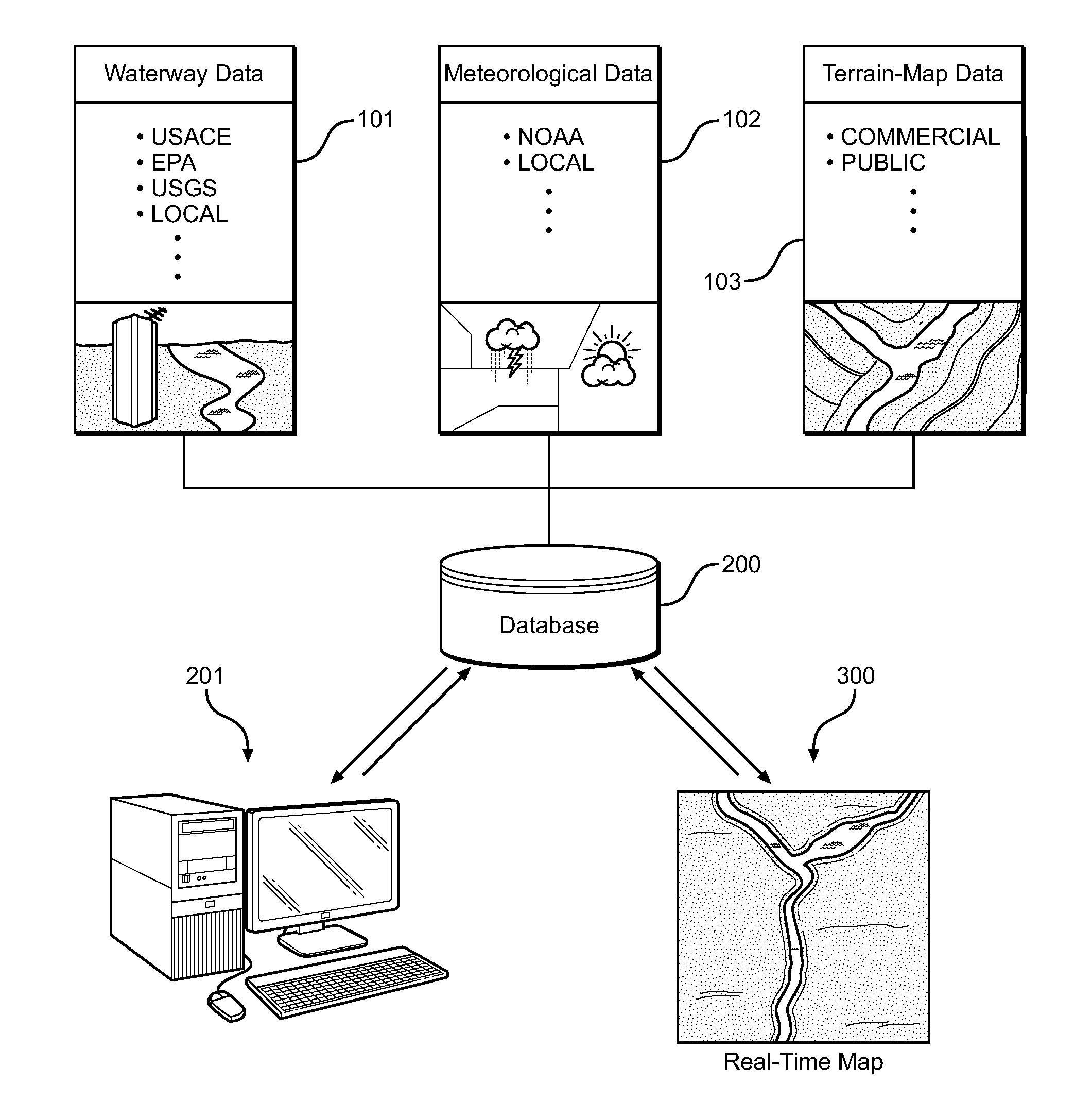
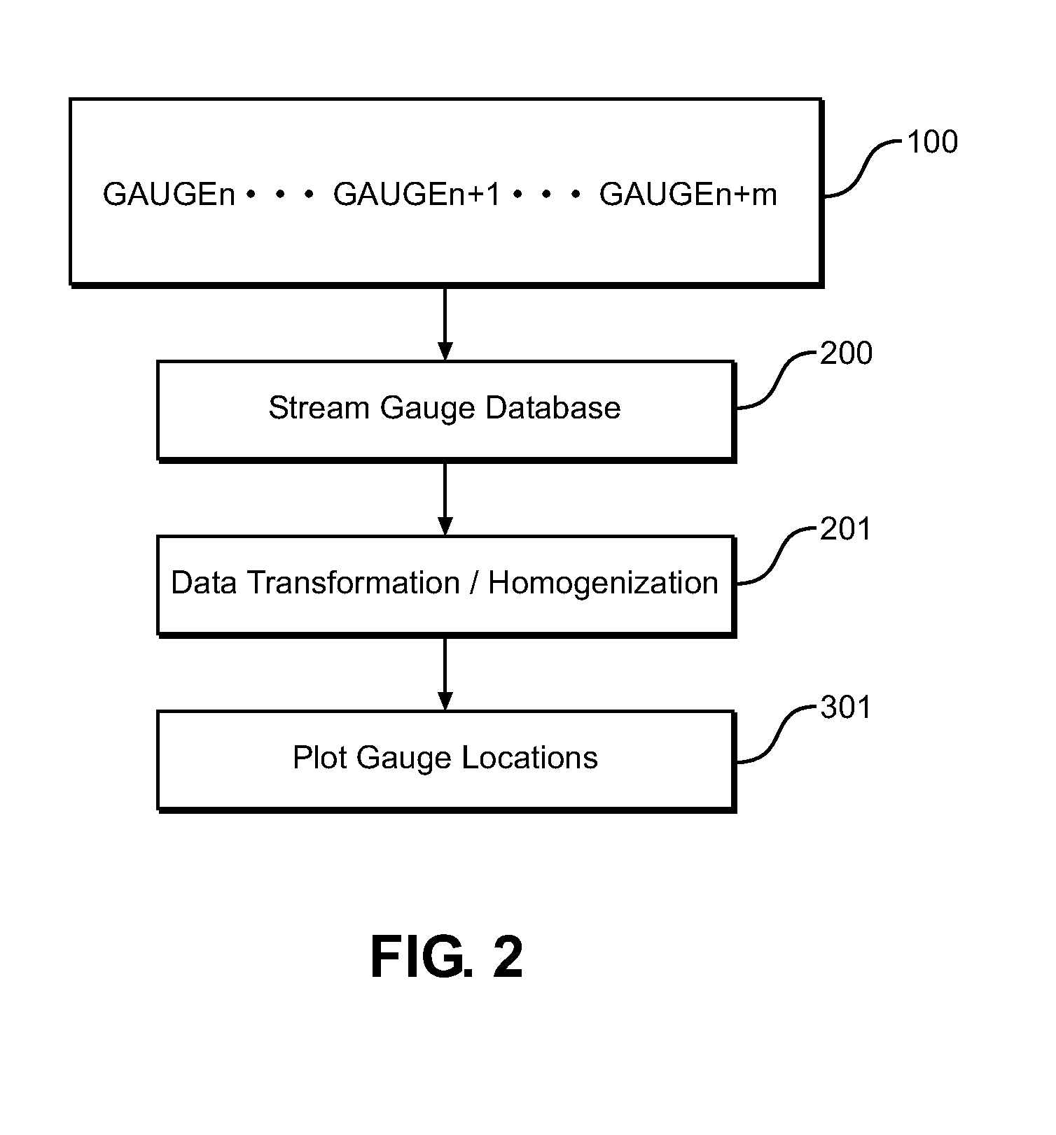
[0030]Reference is made herein to the attached drawings. Like reference numerals are used throughout the drawings to depict like or similar elements of the present flood control method. For the purposes of presenting a brief and clear description of the present invention, the preferred embodiment will be discussed as used for locating flood locations along a waterway, collecting the flooding water, and optionally utilizing the collected water for additional benefits. The figures are intended for representative purposes only and should not be considered to be limiting in any respect.

[0031]The present invention is a method of predicting flood locations along U.S. waterways in which publically available waterway data is gathered and assimilated into a common database and compared against weather data in real-time. The method contemplates mapping the available data on high resolution maps, whereby points along waterways can be monitored and potential flood locations can be identified we...


PUM


Abstract

Provided is a method of identifying and locating high probability areas along a waterway that are likely to flood using real-time data processing of stream gauges and dispatching water capture teams to preventing flooding of the waterway. Water is diverged, blocked, or captured along the waterway to prevent flooding in residential areas. Water is captured in temporary storage devices such as tanks, reservoirs, fabric tube arrays, or available reservoirs, whereafter the collected water can then be analyzed and repurposed after the event. Captured water is tested, treated, and identified. The water can be repurposed or released after the event as necessary. The present method provides a preemptive and long term flood control means for waterways across the country by collecting public source data into a single database, mapping available data points, locating at-risk areas, and coordinating with authorities to divert the water and prepare the local population.

Description

CROSS REFERENCE TO RELATED APPLICATION[0001]This application is a Continuation in Part of U.S. patent application Ser. No. 12 / 845,695 filed on Jul. 28, 2010, entitled “Flood Control Method,” now pending, which claims the benefit of U.S. Provisional Application No. 61 / 229,429, entitled “Flood Control Method” and filed on Jul. 29, 2009. Each patent application identified above is incorporated here by reference in its entirety to provide continuity of disclosure.BACKGROUND OF THE INVENTIONField of the Invention[0002]The present invention relates to a method of mapping waterway data collected from public sources, analyzing the data using a common platform, and identifying potential flood areas in order to prevent the flood from occurring. Flood areas are predicted prior to a storm event such that flood countermeasures can be deployed to those locations for diversion and capture of the flood water, and further for subsequent redistribution of the captured water after the event to regions...

Claims


Application Information

Patent Timeline
Patent Type & Authority Applications(United States)
IPC IPC(8): G01W1/10E02B3/02
CPCE02B3/02G01W1/10G06Q10/06315G06Q50/06E02B3/00Y02A10/40
Inventor HOGAN, RICHARD C.
Owner HOGAN RICHARD C
Why Eureka
Try Eureka