Impeller for centrifugal pump and centrifugal pump of vehicle washer device

a technology of centrifugal pump and impeller, which is applied in the direction of vehicle cleaning, marine propulsion, vessel construction, etc., can solve the problems of reducing the discharge pressure of the blade (impeller) of the centrifugal pump, and the landing point of cleaning liquid squirted from the nozzle onto the front windshield, so as to achieve the effect of suppressing the drop in the discharge pressure of the impeller

Active Publication Date: 2014-02-27
DENSO CORP
View PDF9 Cites 5 Cited by
  • Summary
  • Abstract
  • Description
  • Claims
  • Application Information

AI Technical Summary

Benefits of technology

[0021]According to the centrifugal pump of the vehicle washer device of above aspect, the motor is housed in the motor housing portion of the pump body. The impeller is housed in the pump chamber of the pump body, and is supported on the rotation shaft of the motor so as to be capable of rotating as a unit with the rotation shaft. The liquid (cle...

Problems solved by technology

Since the viscosity of the cleaning liquid increases, for example at low temperatures, there is a possibility of a drop in discharge pressure from the blades (impeller) of the centrifugal pump.
There is accordingly a concer...

Method used


Image

  • Impeller for centrifugal pump and centrifugal pump of vehicle washer device
  • Impeller for centrifugal pump and centrifugal pump of vehicle washer device
  • Impeller for centrifugal pump and centrifugal pump of vehicle washer device

Examples


Embodiment Construction

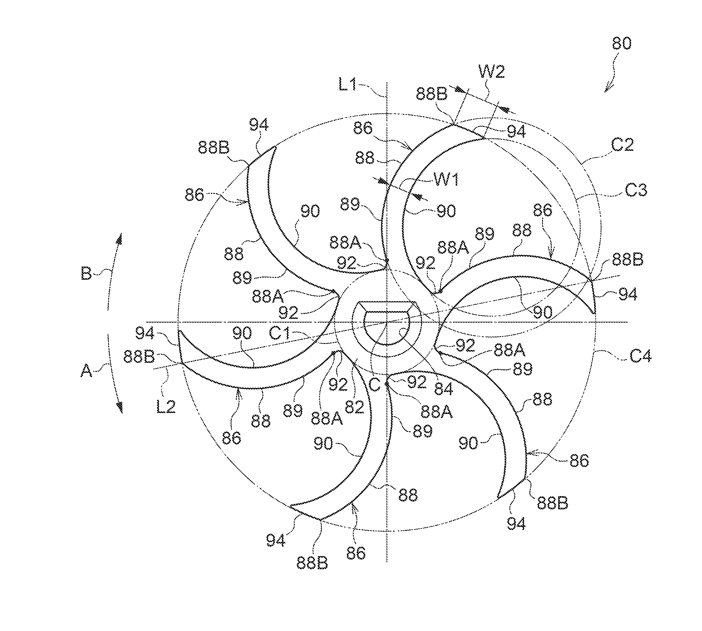
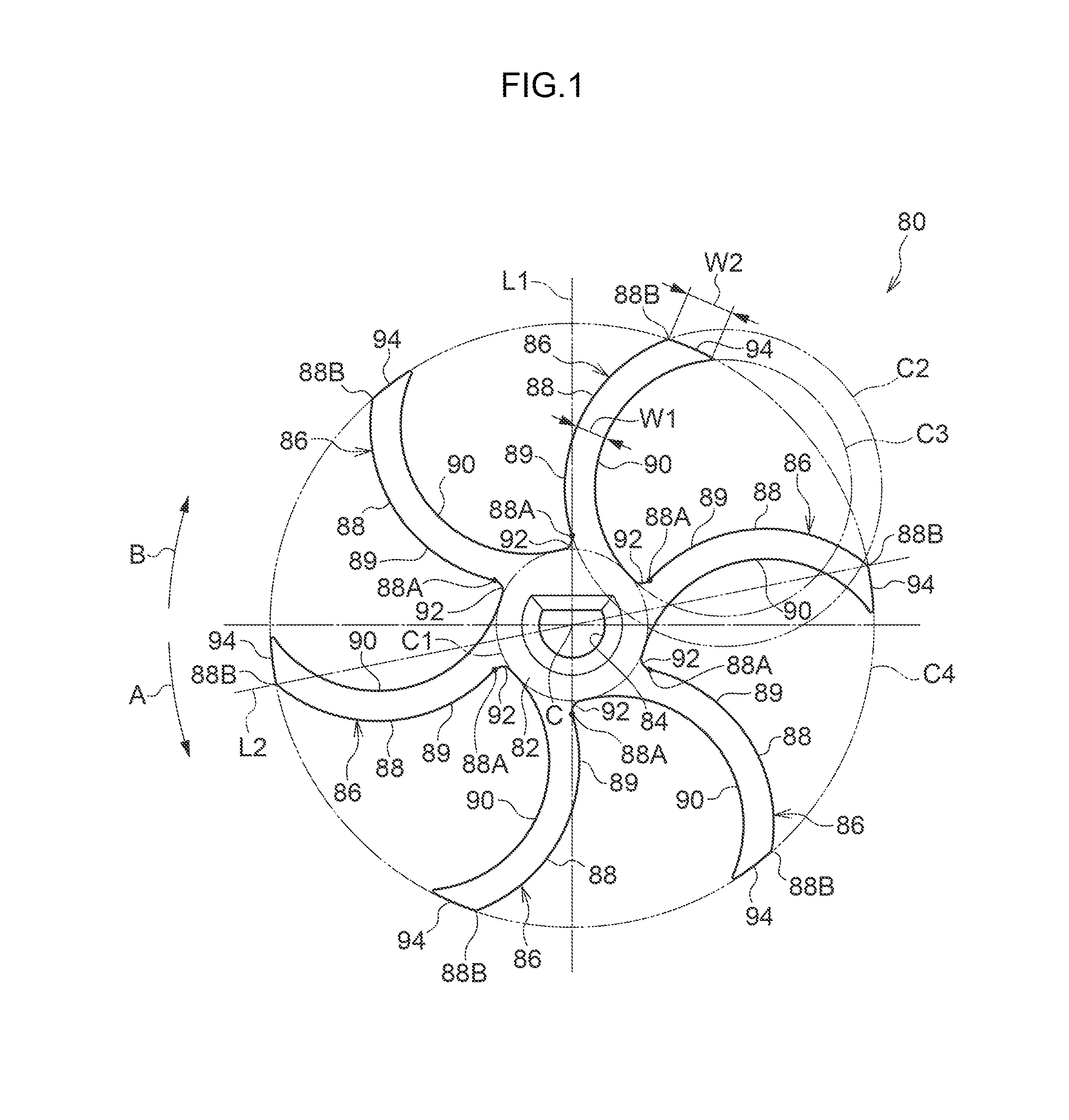
[0033]Explanation follows regarding a centrifugal pump (washer pump) 12 of a vehicle washer device 10 according to a present exemplary embodiment. Explanation then follows regarding an impeller 80 for a centrifugal pump (referred to below as the impeller) employed in the centrifugal pump 12.

[0034]Regarding the Centrifugal Pump 12

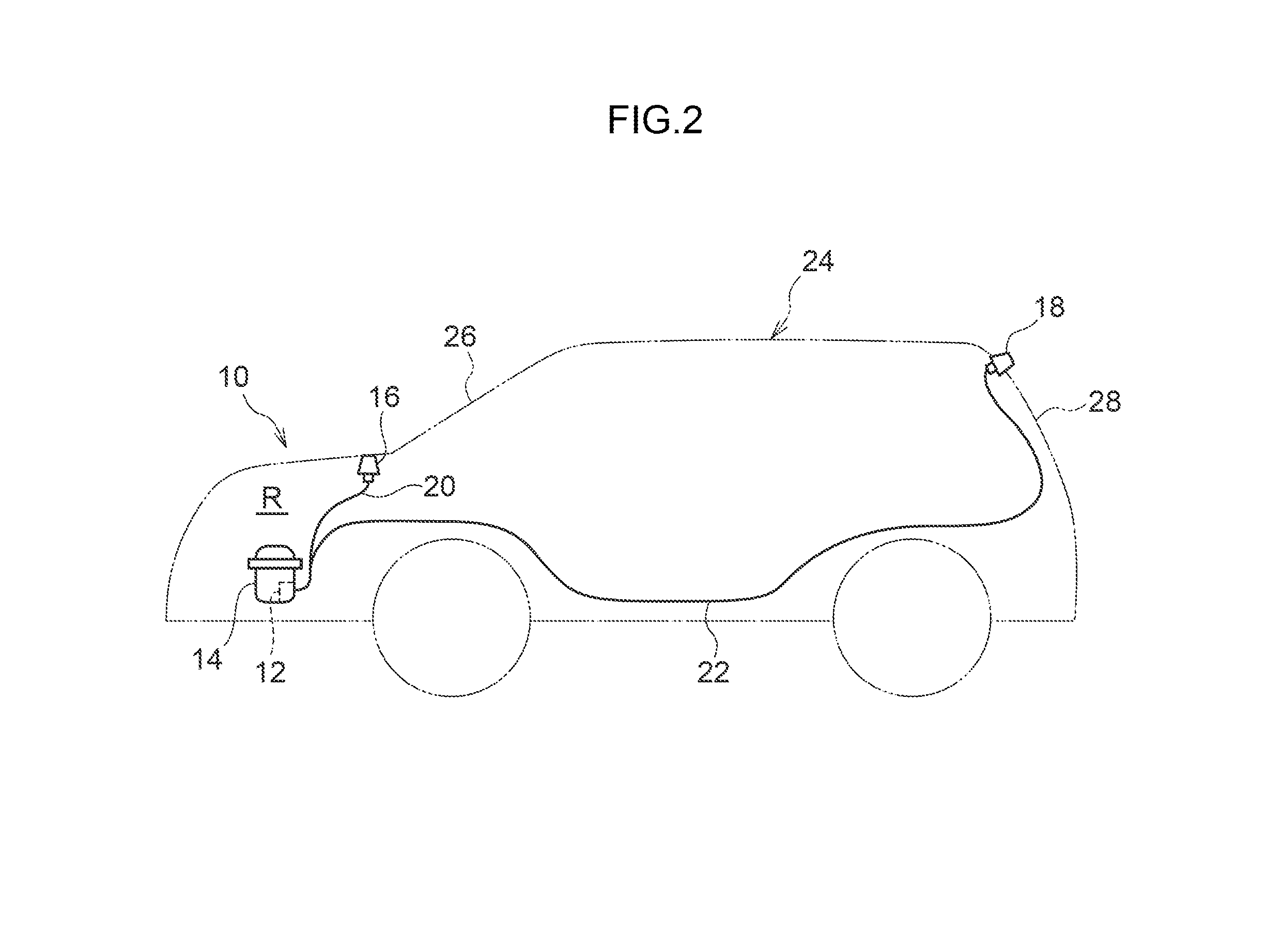
[0035]As illustrated in FIG. 2, the vehicle washer device 10 is applied to a vehicle 24. The vehicle washer device 10 is provided with a washer tank 14 disposed inside an engine room R of the vehicle 24. The centrifugal pump 12 is assembled to the washer tank 14 such that an up-down direction of the centrifugal pump 12 is the same direction as an up-down direction of the vehicle 24. The vehicle washer device 10 also includes a front nozzle 16 for washing a front windshield 26 of the vehicle 24, and a rear nozzle 18 for washing a rear windshield 28 of the vehicle 24. The front nozzle 16 and the rear nozzle 18 are respectively connected to the centrifugal pump...


PUM


Abstract

An impeller for a centrifugal pump comprising a boss supported by a rotation shaft of a motor so as to be rotatable as a unit with the rotation shaft; and a plurality of blades that extend from the boss towards a radial direction outside of the boss, and that discharge liquid towards a leading end side thereof by rotating; wherein each blade comprises one side face that is a face on a first side in a rotation direction of the impeller and includes a projecting face that projects from a base end portion at a boss side of the one side face towards the first side in the rotation direction with respect to a line that connects the base end portion and a center of rotation of the blades.

Description

CROSS-REFERENCE TO RELATED APPLICATION[0001]This application claims priority under 35 USC 119 from Japanese Patent Applications No. 2012-185223 filed Aug. 24, 2012 and No. 2013-006609 filed Jan. 17, 2013, the entire disclosures of which are incorporated by reference herein.BACKGROUND OF THE INVENTION[0002]1. Field of the Invention[0003]The present invention relates to a impeller for a centrifugal pump and a centrifugal pump provided with the impeller of a vehicle washer device.[0004]2. Description of the Related Art[0005]Japanese Patent Application Laid-Open (JP-A) No. H08-261195 describes a centrifugal pump wherein an impeller is fixed to a pump shaft, with the pump shaft rotatably supported inside a casing. The impeller is configured including plural blades, with each blade curved from an inlet end towards a radial direction outside and towards a rotation direction rear side. Intermediate blades are formed in a flow path between the blades, thereby maintaining discharge pressure a...

Claims


Application Information

Patent Timeline
IPC IPC(8): B60S1/48F04D29/22
CPCB60S1/48F04D29/22F04D29/24
Inventor YAMAUCHI, YUUSUKE
Owner DENSO CORP
Why Eureka
Try Eureka