Retention mechanism having improved fatigue strength

a retention mechanism and fatigue strength technology, applied in the field of retention mechanisms, can solve the problems of fatigue failure, surface or retention mechanism or features may encounter wear and tear, etc., and achieve the effects of improving normal force, improving ease of use, and improving retention mechanism

Inactive Publication Date: 2014-02-27
APPLE INC
View PDF2 Cites 29 Cited by
  • Summary
  • Abstract
  • Description
  • Claims
  • Application Information

AI Technical Summary

Benefits of technology

[0005]In view of the shortcomings of some currently available electronic connectors described above, embodiments of the invention relate to connectors with improved retention mechanisms that provide retention forces between an electrical connector plug and a connector receptacle. The retention mechanism may provide an increased normal force between the electrical contacts of the electrical connector plug and the receptacle and improved ease of use by providing a more consistent feel when a connector plug is inserted and extracted from the receptacle. The mechanism includes a retention spring on a first connector, the retention spring having a retaining portion that interfaces and engages with a retention feature of a second connector, the retaining portion and the retention feature being engaged with the first and second connector when mated. In some embodiments, the mechanism includes a retention spring with a distal retaining portion and a proximal reinforced portion having a layer of compressive residual stress so as t...

Problems solved by technology

These interfacing surfaces or retention mechanisms or features may encounter...

Method used


Image

  • Retention mechanism having improved fatigue strength
  • Retention mechanism having improved fatigue strength
  • Retention mechanism having improved fatigue strength

Examples


Embodiment Construction

[0022]The invention will now be described in detail with reference to certain embodiments thereof as illustrated in the accompanying drawings. In the following description, numerous specific details are set forth in order to provide a thorough understanding of the invention. It will be apparent, however, to one skilled in the art, that the invention may be practiced without some or all of these specific details. In other instances, well known details have not been described in detail in order not to unnecessarily obscure the concepts and principles of the invention.

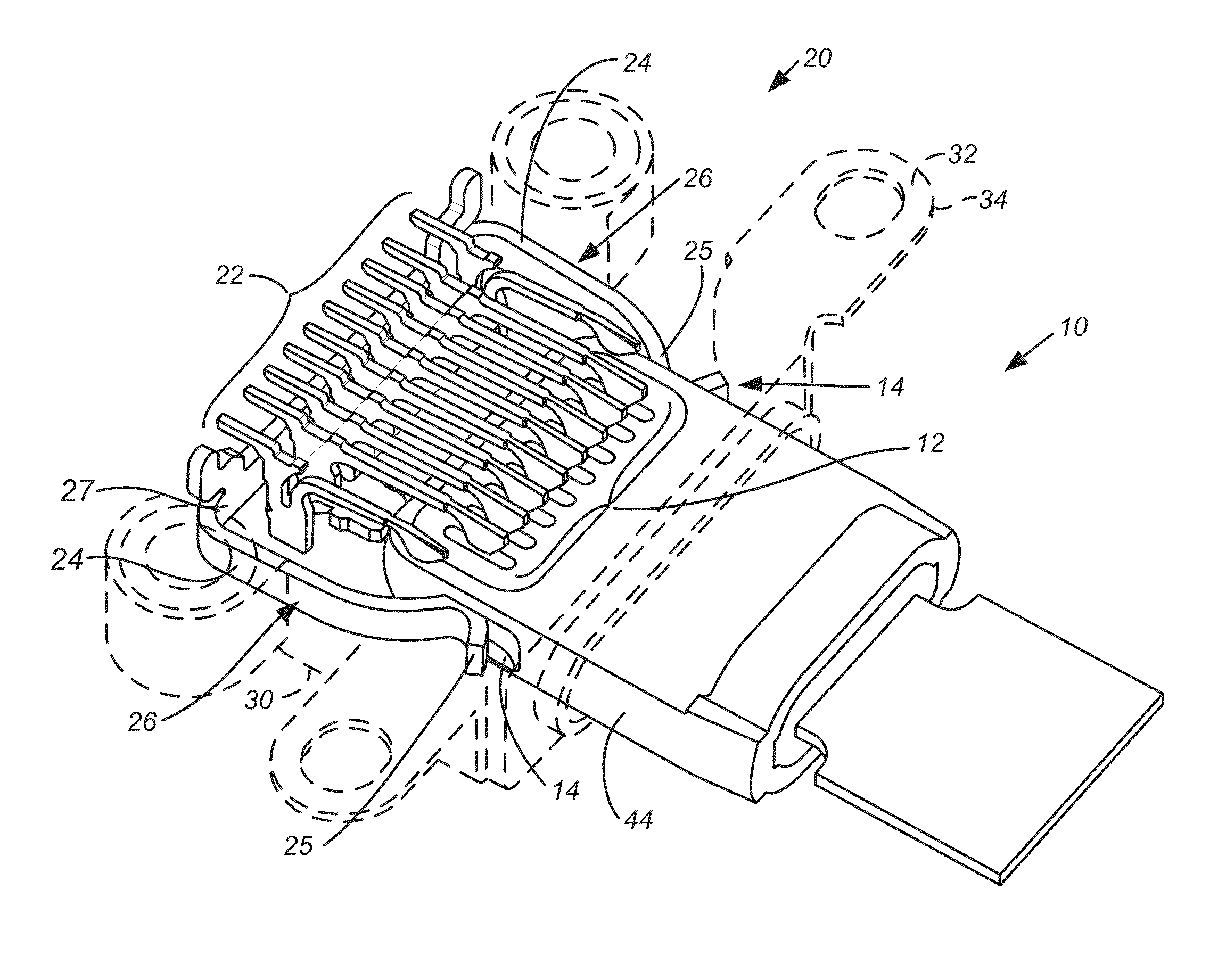
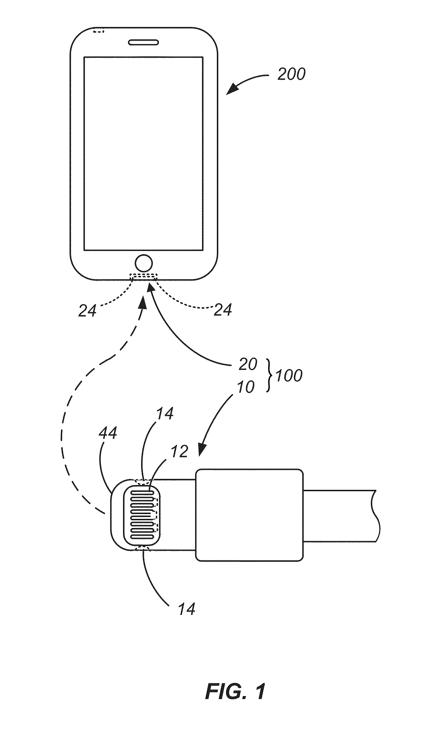
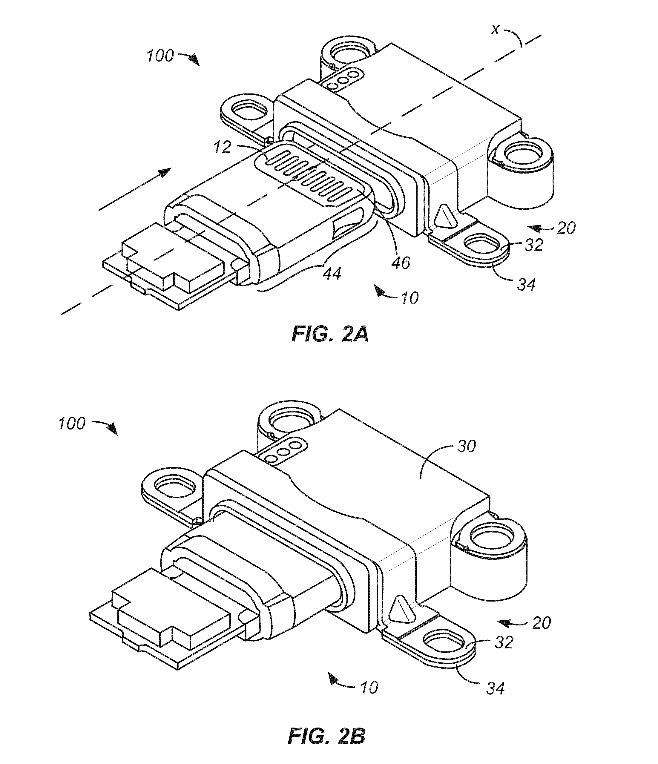
[0023]In order to better appreciate and understand the invention, reference is first made to FIG. 1 which is a simplified schematic representation of connector device 100 having a retention latch mechanism according to an embodiment of the invention. The connector device 100 includes a connector plug 10 insertable into the corresponding connector receptacle 20. The external contact connector plug 10 includes multiple elec...


PUM

PropertyMeasurementUnit
Lengthaaaaaaaaaa
Lengthaaaaaaaaaa
Lengthaaaaaaaaaa

Abstract

A retention latch mechanism having a retention spring of a first connector engageable with a retention feature of a second connector. The retention spring may include a spring arm having a distal, curved retaining portion that is resiliently received within the retention feature and a reinforced portion that is proximal of the distal retaining portion. The reinforced portion includes a layer having residual compressive stress to inhibit fatigue failure during repeated cycling of the latch mechanism. The reinforced portion may be formed by a cold working method, such as shot peening a select region of the spring arm. The reinforced portion is formed to inhibit fatigue failure during repeated cycling of the latch mechanism. Methods of forming a retention mechanism having a retention spring with a reinforced portion are provided herein.

Description

CROSS-REFERENCES TO RELATED APPLICATIONS[0001]This application is a non-provisional of and claims priority to U.S. Provisional Application No. 61 / 693,232 filed on Aug. 24, 2012, the entire contents of which are incorporated herein by reference.BACKGROUND OF THE INVENTION[0002]The invention relates generally to retention mechanisms, and in particular retention mechanisms for use in electrical connectors.[0003]Many devices include electrical connectors to facilitate communication between devices and / or recharging of the device by electrically coupling the device to an external power source. In a typical electrical connector system an electrical connection can be made between a plug connector and a corresponding receptacle connector by inserting the plug connector into the corresponding receptacle connector. Generally, the plug connector includes a group of electrical contacts that engage and electrically couple with corresponding electrical contacts within the receptacle connector whe...

Claims


Application Information

Patent Timeline
IPC IPC(8): H01R13/639H01R43/26
CPCH01R43/26H01R13/639H01R13/6275H01R43/18Y10T29/49208
Inventor WEBER, DOUGLAS J.MATSUYUKI, NAOTO
Owner APPLE INC
Why Eureka
Try Eureka