A process device and method for self-cleaning high-temperature oil and gas filtration and dust removal

A technology for filtration and dust removal and process equipment, which is applied in separation methods, dispersed particle filtration, chemical instruments and methods, etc., can solve the problems of difficult backflushing and regeneration, prone to breakage, large process gas volume, etc., to ensure long-term stable operation, The effect of easy maintenance and repair and meeting technical requirements

Inactive Publication Date: 2017-05-10
SHAANXI MEISILIN ENERGY SCI & TECH RES INST
View PDF8 Cites 0 Cited by
  • Summary
  • Abstract
  • Description
  • Claims
  • Application Information

AI Technical Summary

Problems solved by technology

[0006] (2) Although the non-metallic ceramic filter element used has high filtration accuracy, it has high dust viscosity, difficult back blowing and regeneration, and is prone to breakage at high temperature
[0007] (3) The process gas volume to be processed by the filter device is large, the number of filter elements required is large, and the diameter of the filter is large

Method used


Image

  • A process device and method for self-cleaning high-temperature oil and gas filtration and dust removal
  • A process device and method for self-cleaning high-temperature oil and gas filtration and dust removal
  • A process device and method for self-cleaning high-temperature oil and gas filtration and dust removal

Examples


Embodiment 1

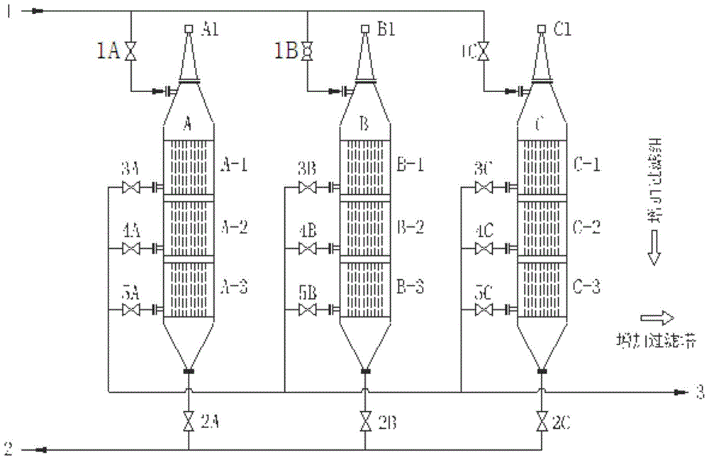
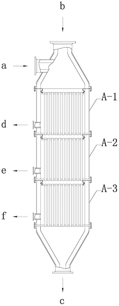
[0052] see Figure 1 to Figure 3 , a process method for self-cleaning high-temperature oil and gas filtration and dust removal based on the process device, comprising the following steps:

[0053] 1. The 800°C high-temperature oil and gas 1 from a known pyrolysis device is distributed to filter towers A, B, and C through pipelines. Due to the parallel operation of the filter towers, the process is described by taking Tower A as an example.

[0054] 2. High-temperature oil and gas 1 enters tangentially from the high-temperature oil-gas interface on the top side of filter tower A through feed gas cut-off valve 1A. The high-temperature oil and gas 1 flows from top to bottom inside the filter tower A, and passes through the tower filter groups A-1, A-2, and A-3 for purification. During this process, most of the gas penetrates through the inner surface of the filter element, and the temperature of the purified gas drops to 760°C due to the heat dissipation effect of the pipeline ...

Embodiment 2

[0059] see Figure 1 to Figure 3 , a process method for self-cleaning high-temperature oil and gas filtration and dust removal based on the process device, comprising the following steps:

[0060] 1. The 520°C high-temperature oil and gas 1 from the known pyrolysis device is distributed to filter towers A, B, and C through pipelines. Due to the parallel operation of the filter towers, the process is described by taking Tower A as an example.

[0061] 2. High-temperature oil and gas 1 enters tangentially from the high-temperature oil-gas interface on the top side of filter tower A through feed gas cut-off valve 1A. The high-temperature oil and gas 1 flows from top to bottom inside the filter tower A, and passes through the tower filter groups A-1, A-2, and A-3 for purification. During this process, most of the gas passes through the inner surface of the filter element, and the temperature of the purified gas drops to 470°C due to the heat dissipation effect of the pipeline an...

Embodiment 3

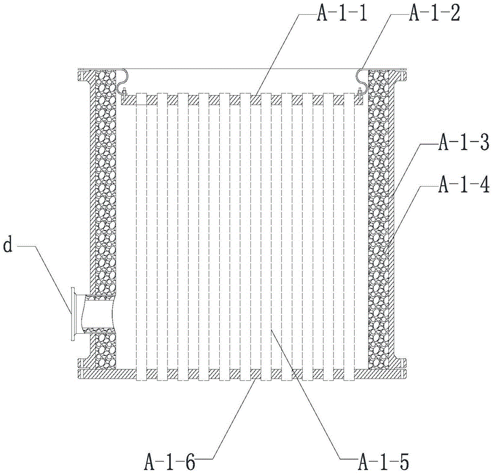
[0066]The 650°C high-temperature oil and gas 1 from the double-circulating fluidized bed pyrolysis unit is distributed through pipelines to three filter towers A, B, and C operating in parallel. Now take tower A as an example to describe the process. High temperature oil gas 1 enters from the top of filter tower A in a conical shape through feed gas cut-off valve 1A. The high-temperature oil and gas 1 flows from top to bottom inside the filter tower A, and passes through the tower filter groups A-1, A-2, and A-3 in sequence. According to the particle size characteristics of high-temperature oil and gas dust, the filter elements of tower filter groups A-1, A-2, and A-3 (for example, the filter element of tower A-1 tower filter group is A-1-5) select the inner surface of the filter element membrane The metal multi-layer sintered mesh for filtering, the filter element (A tower A-1 tower filter group as an example, the filter element is A-1-5) has a filtration accuracy of 30 micro...


PUM

PropertyMeasurementUnit
diameteraaaaaaaaaa
lengthaaaaaaaaaa

Abstract

The invention discloses a self-cleaning high-temperature oil gas filter dust-removal process device and method. The device comprises a plurality of filter towers connected in parallel, wherein each filter tower comprises an upper seal head, a lower seal head and a plurality of tower filter groups which are perpendicularly stacked and the same; upper seal heads of which the side surfaces are provided with high-temperature oil gas connectors are arranged at the upper ends of the perpendicularly stacked tower filter groups; the lower seal heads provided with dust-containing exhaust connectors are arranged at the lower ends of the perpendicularly stacked tower filter groups; the upper ends of the filter towers are connected in parallel through the high-temperature oil gas connectors; the lower ends of the filter towers are connected in parallel through the dust-containing exhaust connectors; a filter group purified-gas connector is formed in each tower filter group; the filter tower groups are connected in parallel through the filter group purified-gas connectors. According to the invention, after the device adopts a tower structure, the process device with a reasonable height-diameter ratio can be designed; after the high-temperature pyrolysis oil gas treated by the self-cleaning high-temperature oil gas filter dust-removal process device and method is recovered, the solid content of coal tar is less than 0.5 mg / L, so that the technical requirements of coal tar deep-processing process are completely met.

Description

technical field [0001] The invention belongs to the fields of coal chemical industry, oil shale and biomass pyrolysis, and specifically relates to a process device and method for self-cleaning high-temperature oil and gas filtration and dust removal. Background technique [0002] Energy is the driving force for a country's economic and social development, and my country's energy structure of rich coal, little oil, and lack of gas determines that coal can only be the mainstay. In recent years, domestic demand for fuel oil has increased rapidly with economic development, and pulverized coal Pyrolysis technology develops rapidly. Coal tar is extracted before coal combustion or gasification. Coal tar is further processed to produce gasoline and diesel oil. The quality of coal resources is used to reduce the emission of nitrogen oxides and sulfides in exhaust gas, thereby increasing the added value of coal. This technology has epoch-making significance for coal-fired power plants. ...

Claims


Application Information

Patent Timeline
Patent Type & Authority Patents(China)
IPC IPC(8): B01D46/00B01D46/42B01D46/24
Inventor 佘焱董芳儒
Owner SHAANXI MEISILIN ENERGY SCI & TECH RES INST
Why Eureka
Try Eureka