
Connection structure for flexible circuit cable

a flexible circuit cable and connection structure technology, applied in the direction of connection, electrical apparatus, coupling device connection, etc., can solve the problems of poor connection that affects the transmission of signals, complicated connector structure, increased manufacturing cost, etc., to reduce manufacturing cost, improve the insertion connection structure of flexible circuit cable, and improve the effect of deficiencies

Active Publication Date: 2014-02-27
ADVANCED FLEXIBLE CIRCUITS
View PDF0 Cites 6 Cited by
  • Summary
  • Abstract
  • Description
  • Claims
  • Application Information

AI Technical Summary

Benefits of technology

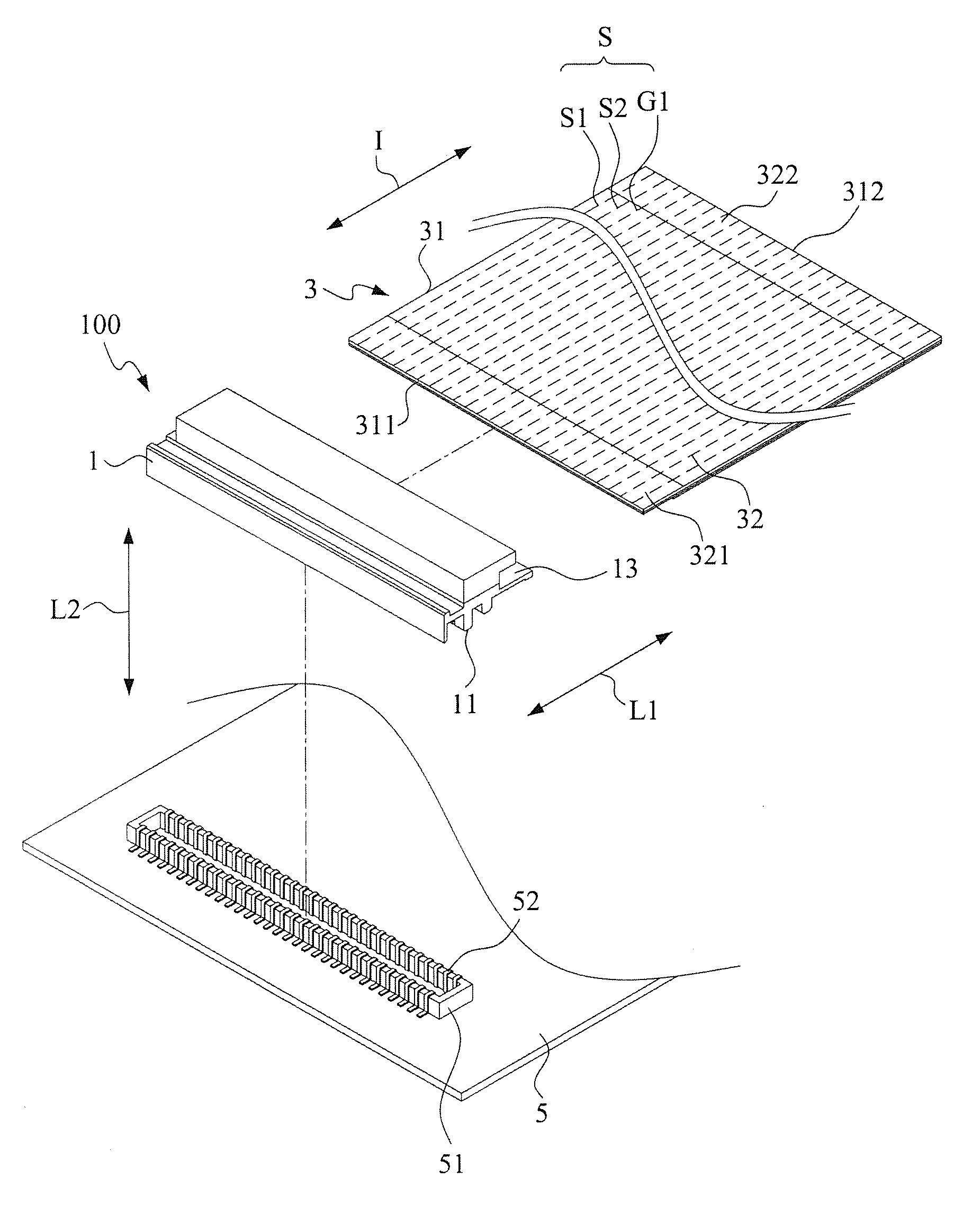
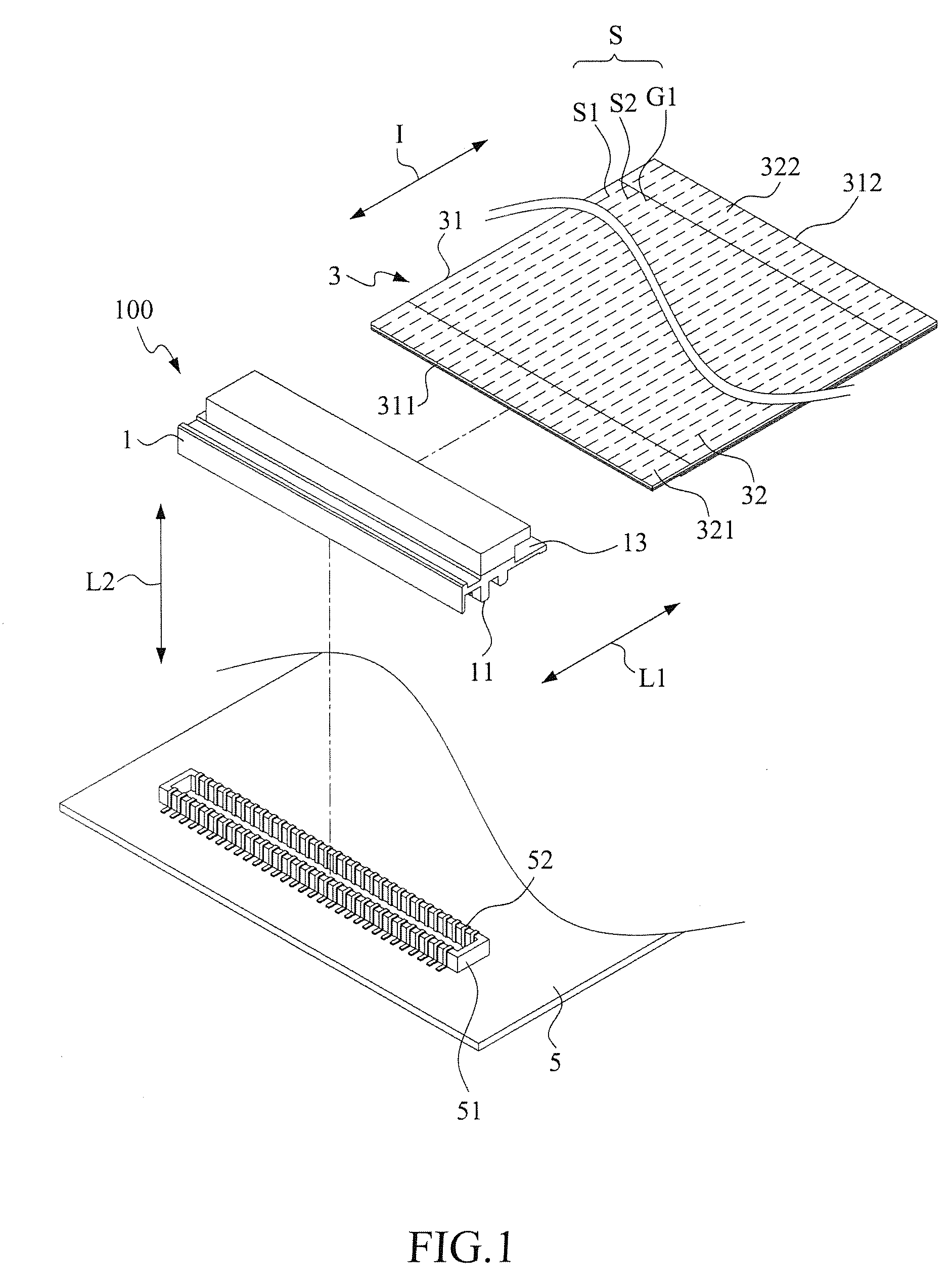
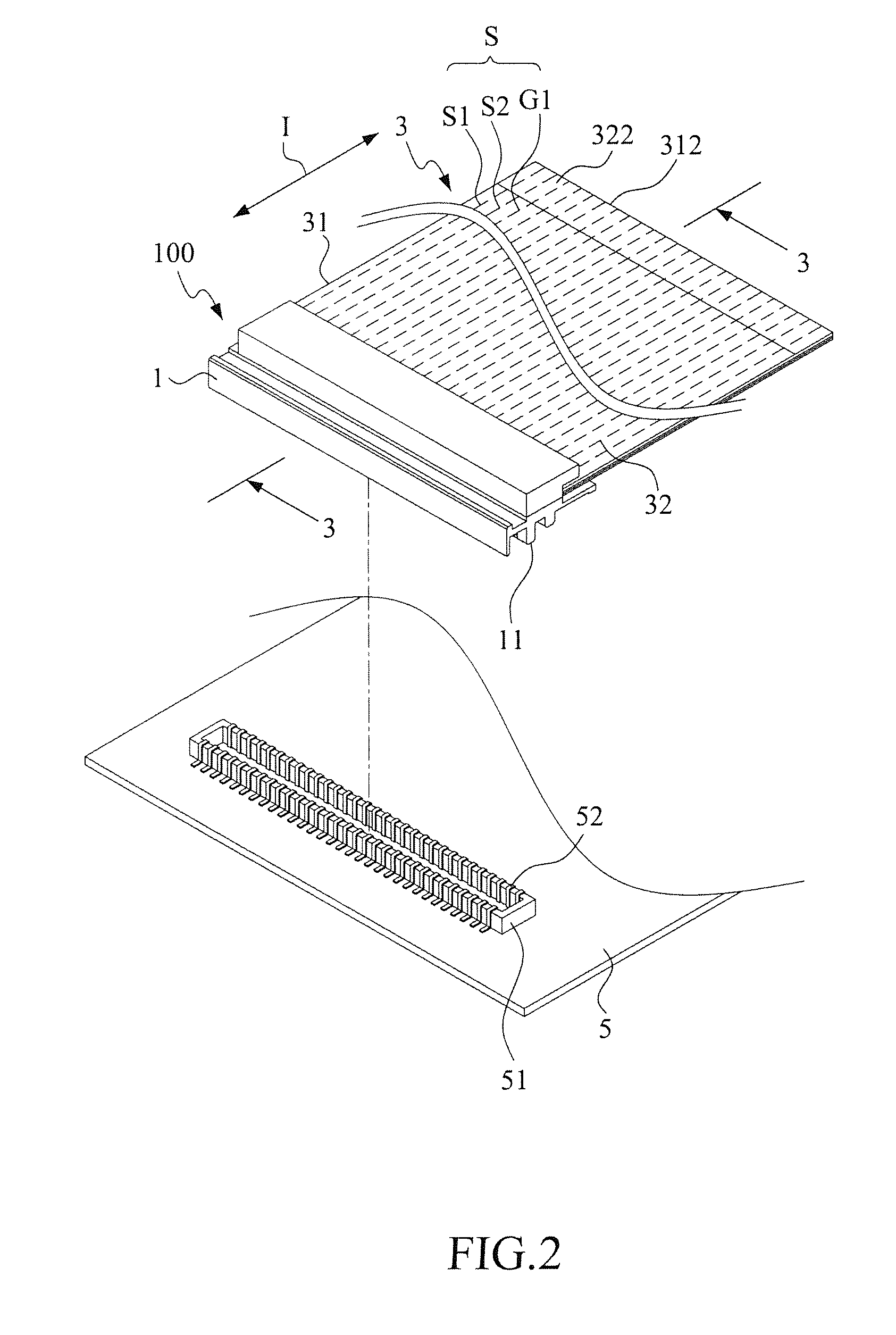
The present invention provides a connection structure of flexible circuit cable using a soldering layer to bond the cable to a connector and improve its deficiencies. This structure allows for more flexibility in design and arrangement of circuits, reducing the amount of space needed and facilitating the design of compact and light-weight electronic devices. Compared to conventional connectors, the insertion connection structure of flexible circuit cable is simple and reduces manufacturing costs.

Problems solved by technology

This results in poor connection that affects transmission of signals.
However, such a technique makes the connector structure complicated and manufacturing cost increased.

Method used


Image

  • Connection structure for flexible circuit cable
  • Connection structure for flexible circuit cable
  • Connection structure for flexible circuit cable

Examples


fifth embodiment

[0048]In the embodiment of FIG. 12, the number and width of the second finger pad conductive contacts 322 provided on the second end 312 of the flexible circuit cable 3 are generally identical to those of the cable contacts 361 of the extension circuit cable 36. However, variations can be made on such a basic arrangement according to the present invention. For example, FIG. 15 shows a schematic view of a fifth embodiment according to the present invention, in which the number of the second finger pad conductive contacts 322 of the second end 312 of the flexible circuit cable 3 is less than that of the first finger pad conductive contacts 321 of the first end 311, but the second end 312 and the first end 311 are set to be of identical width, whereby the pitch or spacing distance between the contacts of the second end 312 is widened. To achieve such an arrangement, via holes 37 and connection lines 38 are arranged in the flexible circuit cable 3 to allow some of the first finger pad c...

sixth embodiment

[0049]Further, FIG. 16 shows a schematic view of a sixth embodiment according to the present invention, in which the number of the second finger pad conductive contacts 322 at the second end 312 of the flexible circuit cable 3 is less than that of the first finger pad conductive contacts 321 at the first end 311 and the width of the second end 312 is smaller than the first end 311. To achieve such an arrangement, the same structure constituted by via holes 37 and connection lines 38 can be used. The width of the extension circuit cable 36 can thus be made smaller, which, together with slit lines formed in extension circuit cable 36 and corresponding bundling structure, facilitates passage through a bore of a hinge or a narrow hole.

[0050]The present invention provides the following advantages:

[0051](1) The present invention uses a soldering layer to bond a flexible circuit cable to a soldering section of a connector so as to securely fix conductive lines of the flexible circuit cable...


PUM


Abstract

A connection structure for a flexible circuit cable includes a flexible circuit cable that has a flexible circuit substrate having a first end bonded to a soldering stage of the connector housing with first finger pad conductive contacts of conductive lines of the flexible circuit cable respectively corresponding to cable soldering sections of metal conductive terminals of the connector. A soldering layer is formed between a metal coating layer of the first finger pad conductive contact of each of the conductive lines and the cable soldering section of the corresponding metal conductive terminals to set the conductive lines of the flexible circuit cable in electrical connection with the metal conductive terminals of the connector.

Description

BACKGROUND OF THE INVENTION[0001]1. Field of the Invention[0002]The present invention relates to the design of structure of signal transmission circiuit cable, and in particular to an insertion connection structure for a flexible circuit cable.[0003]2. The Related Arts[0004]Connectors are commonly used in circuit arrangements of various electronic devices, such as computer devices, mobile phones, digital cameras, GPS, LCD panels, inspection devices, and control devices, to connect signal lines, coaxial cables, or connection flat cables to circuit boards, circuit modules, or electrical devices for transmission of electrical signals.[0005]A connector is a connection device that electrically connects an electrical wire, a circuit board, and other electrical components and provides a function of separable interface for connection two sub-systems of an electronic system to effect transmission of signal or power. Generally, a connector is soldered on a circuit board in such a way that ter...

Claims


Application Information

Patent Timeline
Patent Type & Authority Applications(United States)
IPC IPC(8): H01R12/62
CPCH01R4/024H01R12/594H01R12/65H01R12/79
Inventor SU, KUO-FULIN, GWUN-JINCHUO, CHIH-HENG
Owner ADVANCED FLEXIBLE CIRCUITS
Learn More