Thermal Storage System and Power Generation System Including the Same
a technology of thermal storage and power generation system, which is applied in the direction of steam engine plants, propulsion parts, machines/engines, etc., can solve the problems of environmental destruction, major problems, and countermeasures against depletion of earth resources, and achieve the effect of more efficient solar thermal energy utilization
- Summary
- Abstract
- Description
- Claims
- Application Information
AI Technical Summary
Benefits of technology
Problems solved by technology
Method used
Image

Examples
first embodiment
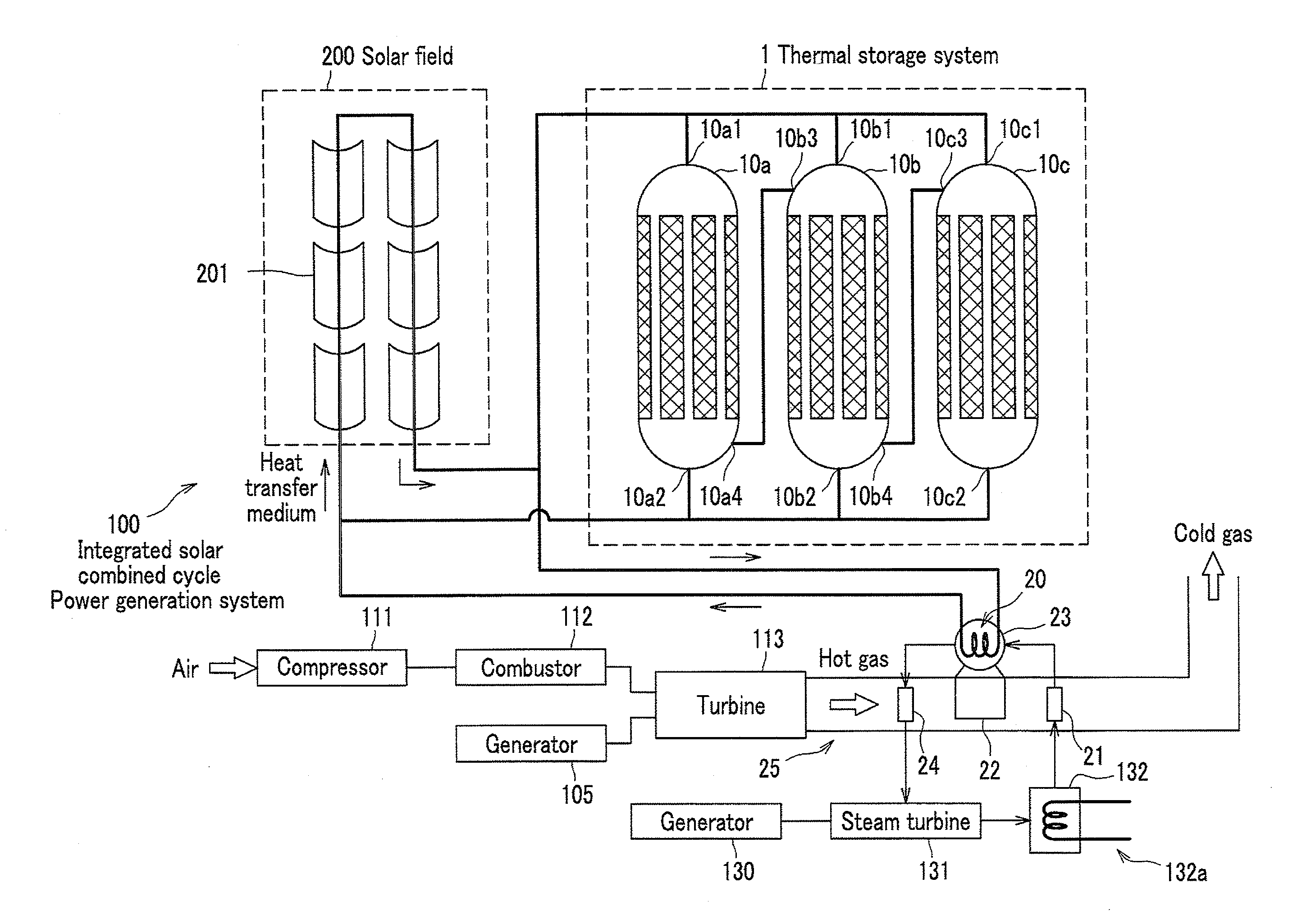
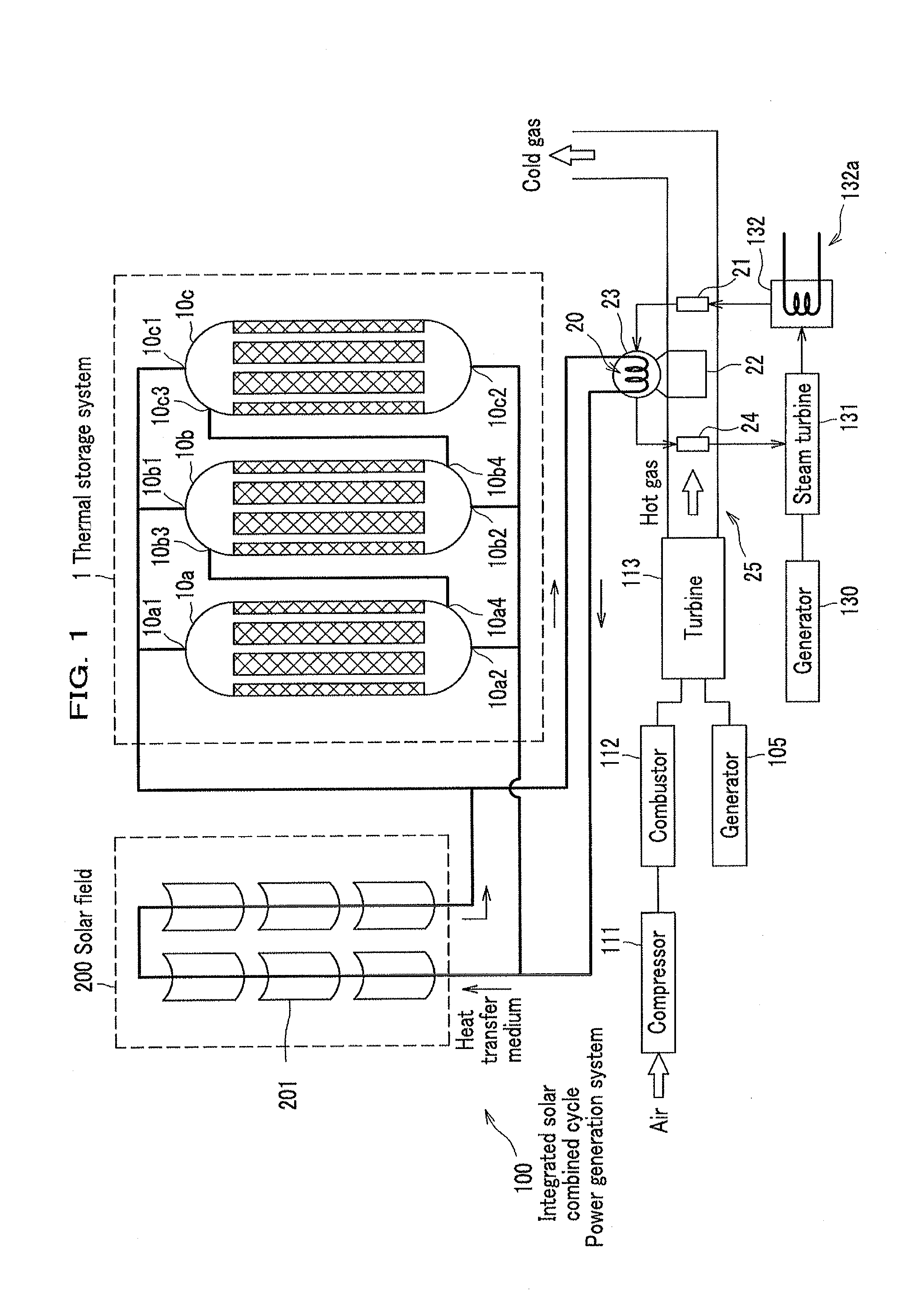
[0024]A thermal storage system of the present embodiment is used for storing the solar thermal energy. The thermal storage system according to the present embodiment can be provided in a power generation system as appropriate. Then, the present embodiment will be described first in an integrated solar combined cycle power generation system as a specific example of a power generation system. An integrated solar combined cycle power generation system includes a turbine (gas turbine) and a steam turbine, for generating power therewith.
[0025]
[0026]As shown in FIG. 1, a power generation system according to the first embodiment includes a thermal storage system 1, and an integrated solar combined cycle power generation system 100 (hereinafter referred to simply as “power generating system 100”) to which the thermal storage system 1 is applied. Heat transfer medium is circulated between the thermal storage system 1 and the power generation system 100, through a pipe (not shown). Bold lines...
second embodiment
[0070]Next, description will be given of a thermal storage system according to the second embodiment (thermal storage system 2), with reference to FIGS. 6 and 7. Assuming that the same item as the first embodiment is denoted by the same reference numeral, and detailed description thereof will be omitted. In addition, the power generation system 300, in which the thermal storage system 2 shown in FIG. 6 is applied, has the same configuration as the power generation system 100 described above.
[0071]The thermal storage system 2 is provided with a stratified tank 15 that does not include phase-change material, in addition to the stratified tanks 10a-10c. That is, the stratified tank 15 (a second thermal storage tank) is intended for storing the heat transfer medium itself which has absorbed the solar thermal energy. The stratified tank 15 is connected in parallel to the solar field 200. Similarly, the stratified tank 15 is connected in parallel even to the stratified tanks 10a-10c. In a...
third embodiment
[0076]Next, description will be given of a thermal storage system (thermal storage system 3) according to a third embodiment, by referring to FIG. 8. In FIG. 8, the same items as the respective embodiments described above shall be denoted by the same reference numerals, and detailed descriptions thereof will be omitted.
[0077]In the thermal storage system 3, four stratified tanks 10a-10d and one stratified tank 15 are connected in parallel, as shown in FIG. 8A. Note that the stratified tank 10d is the same as the aforesaid stratified tanks 10a-10c. Then, during the thermal storage period, as is the case with the respective embodiments described above, the heat transfer medium flows through the stratified tanks 10a-10d, and 15, for storing the heat.
[0078]However, a predetermined control is performed after the thermal storage period but before the heat radiation is performed using the stratified tanks 10a-10d. In other words, while the emission of the heat transfer medium (use of the s...
PUM
 Abstract
Description
Claims
Application Information
 - R&D
- Intellectual Property
- Life Sciences
- Materials
- Tech Scout
- Unparalleled Data Quality
- Higher Quality Content
- 60% Fewer Hallucinations
Browse by: Latest US Patents, China's latest patents, Technical Efficacy Thesaurus, Application Domain, Technology Topic, Popular Technical Reports.
© 2025 PatSnap. All rights reserved.Legal|Privacy policy|Modern Slavery Act Transparency Statement|Sitemap|About US| Contact US: help@patsnap.com