Pedaling force measurement device

a technology of pedaling force and measurement device, which is applied in the direction of force/torque/work measurement apparatus, cycle equipment, instruments, etc., can solve the problems of difficulty in measuring a single parameter and errors in the detected output for one parameter, so as to simplify the configuration of the pedaling force measurement device, suppress interference in one parameter, and suppress errors in the detected parameter

Active Publication Date: 2014-03-06
SHIMANO INC +1
View PDF2 Cites 54 Cited by
  • Summary
  • Abstract
  • Description
  • Claims
  • Application Information

AI Technical Summary

Benefits of technology

[0037]A pedaling force measurement device according to a twenty-third aspect of the present invention is the pedaling force measurement device according to one of the first through the eighteenth aspects, wherein the strain-flexing part is integrally formed with the crank arm. In this case, there is no need to provide a separate strain-flexing part, simplifying the configuration of the pedaling force measurement device.
[0038]According to the present invention, it is possible to suppress interference in one parameter out of a plurality of pedaling force parameters acting upon a crank arm via a pedal being pushed from other parameters, and to suppress errors in the detected parameter. It is thus possible to precisely measure pedaling force parameters.

Problems solved by technology

It is difficult to measure a single parameter, such as a bending moment force component, with high precision using a conventional pedaling force measurement device due to the influence of the other parameters.
At this time, errors in the detected output for one parameter may arise due to one parameter being subjected to interference from the other parameters.

Method used


Image

  • Pedaling force measurement device
  • Pedaling force measurement device
  • Pedaling force measurement device

Examples


second embodiment

[0121]In the first embodiment, the present invention was described using an example of a crank arm having a constant crank length, but, in a second embodiment, the present invention will be described using an example of a crank arm having a variable crank length.

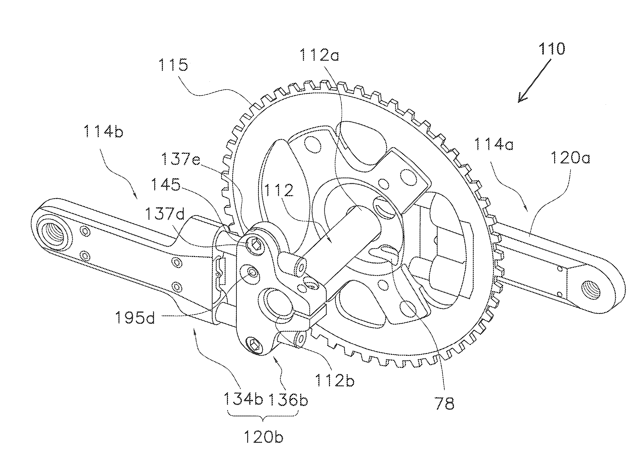
[0122]As shown in FIG. 13, a second pedaling force measurement device 114a is provided toward the front side of the drawing in the second embodiment.

[0123]A crank assembly 110 used in the second embodiment of the present invention is provided with a crank shaft 112, configured similarly to that of the first embodiment, having a first end 112a and a second end 112b, a first pedaling force measurement device 114a, a second pedaling force measurement device 114b, and a sprocket 115. A cadence sensor 78 is provided on a surface of a first crank arm 120a upon which the sprocket 115 is provided facing a second crank arm 120b. A cadence sensor 78 is similarly provided on a surface of the second crank arm 120b facing the first crank...


PUM

PropertyMeasurementUnit
total lengthaaaaaaaaaa
force measurementaaaaaaaaaa
pedaling forceaaaaaaaaaa

Abstract

A first pedaling force measurement device measures a plurality of pedaling force parameters acting on a first crank arm to one end of which a first pedal can be attached and to another end of which a crank shaft can be attached. The first pedaling force measurement device is provided with a strain-flexing part, a first parameter detection part and a first interference suppression part. Strain acting on the first crank arm is conveyed to the strain-flexing part. The parameter detection part is disposed on the strain-flexing part, and detects a plurality of parameters based on the strain being conveyed to the strain-flexing part. The interference suppression part suppresses interference in one parameter detected by the parameter detection part from the other parameters.

Description

GROSS-REFERENCE TO RELATED APPLICATIONS[0001]This application claims priority to Japanese Patent Application No. 2012-188126, filed on Aug. 28, 2012. The entire disclosure of Japanese Patent Application No. 2012-188126 is hereby incorporated herein by reference.BACKGROUND[0002]1. Field of the Invention[0003]This invention generally relates to a pedaling force measurement device for measuring a plurality of parameters for pedaling force acting on a crank arm having a pedal attachable on one end and a crankshaft attachable on the other end, the pedaling force being due to the pedal being pushed.[0004]2. Background Information[0005]Pedaling force measurement devices are known in the prior art for measuring pedaling force acting on a bicycle crank arm in terms of a plurality of parameters due to a pedal being pushed (for example, see PCT International Publication No. WO / 2011 / 030215). In a conventional pedaling force measurement device, parameters in the for of a vertical force component...

Claims


Application Information

Patent Timeline
Patent Type & Authority Applications(United States)
IPC IPC(8): G01L1/22
CPCG01L1/22G01L3/247B62J45/411B62J45/421B62M3/00
Inventor TETSUKA, TOSHIOSATOARAI, TORULI, KUI
Owner SHIMANO INC
Why Eureka
Try Eureka