Fiber Reinforced Concrete
a technology of reinforced concrete and fibers, which is applied in the direction of transportation and packaging, sustainable waste treatment, solid waste management, etc., can solve the problems of concomitant compromising resistance, little or no concrete strength, and problematic reinforcing methods
- Summary
- Abstract
- Description
- Claims
- Application Information
AI Technical Summary
Benefits of technology
Problems solved by technology
Method used
Image
Examples
example 1
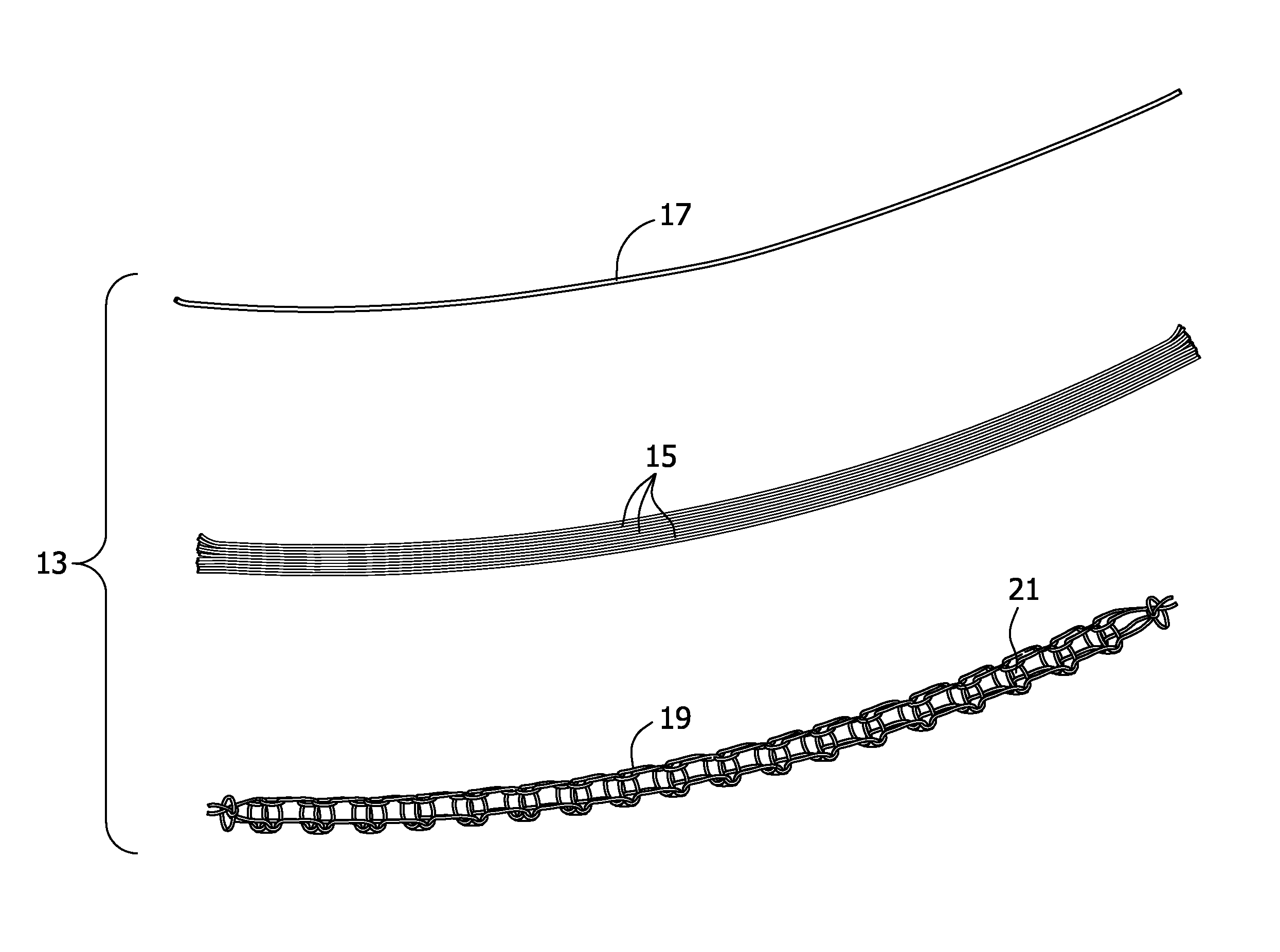
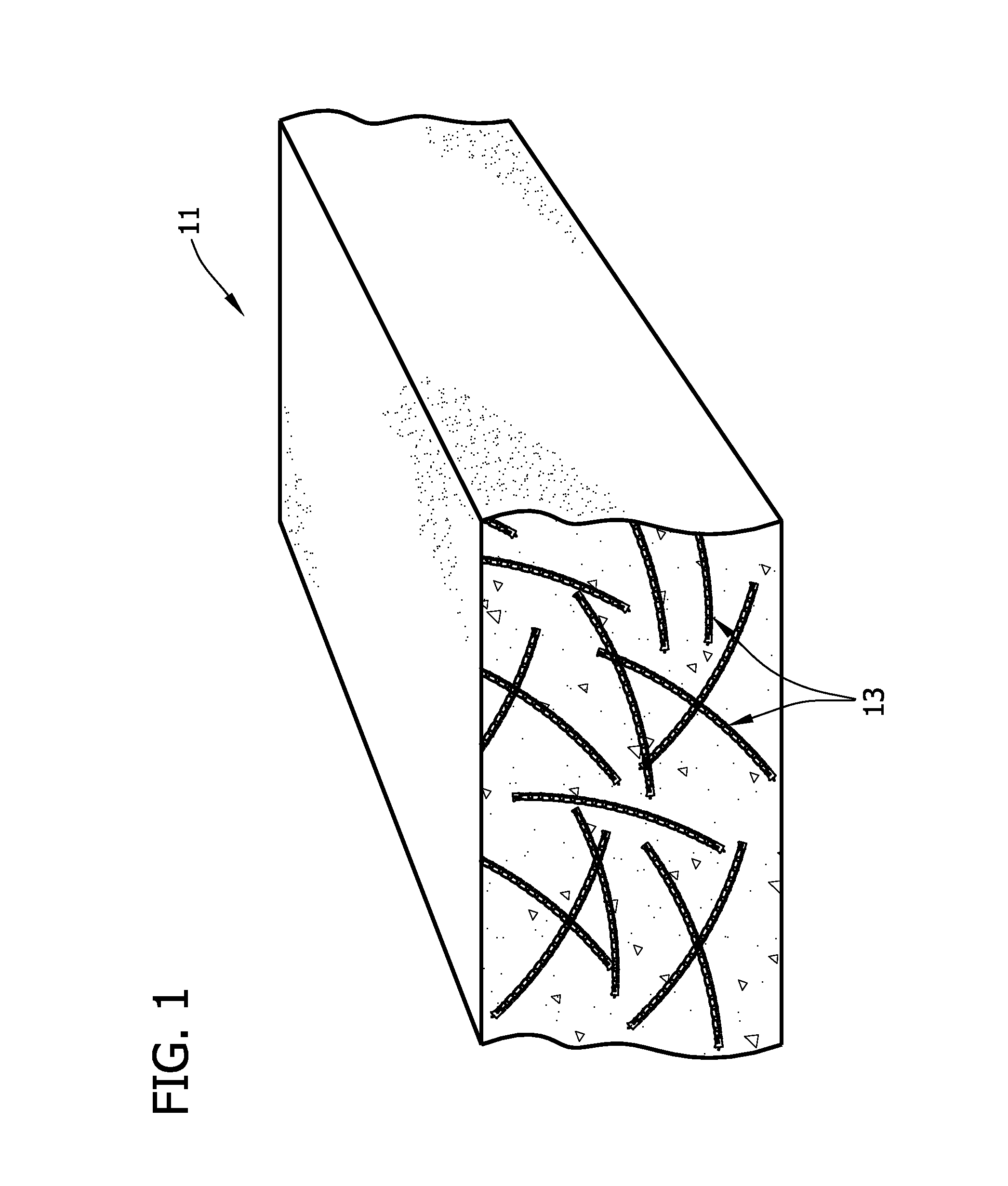
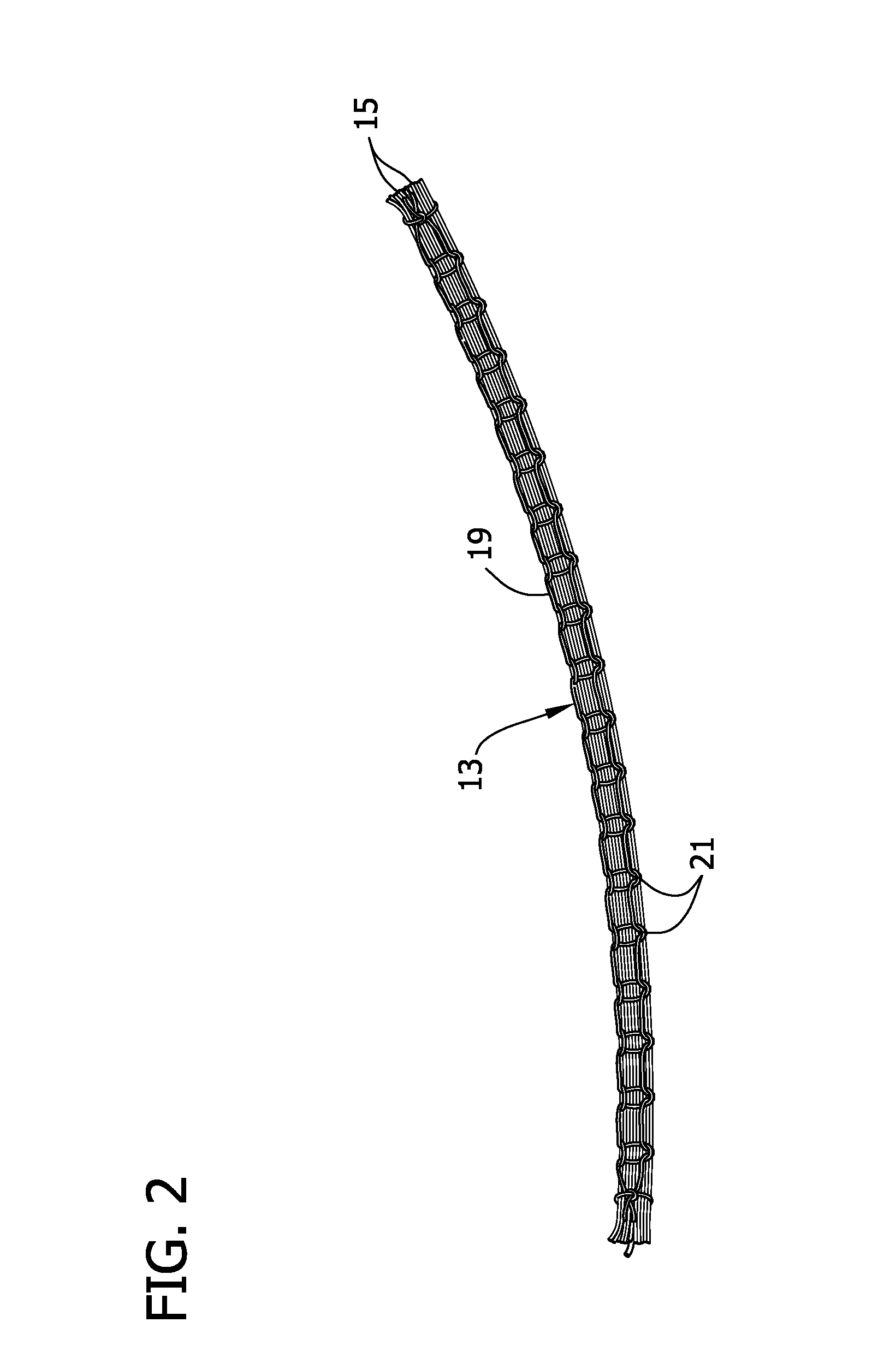
[0057]Various carbon fiber types and assembly structures were evaluated for capability to reinforce concrete.
[0058]Each concrete slab evaluated in Example 1 was prepared from a concrete base mix comprising cement (605 kg / m3), crushed limestone coarse aggregate (19 mm maximum) (783 kg / m3), fine sand aggregate (783 kg / m3) and water (230 kg / m3) was used. A superplasticizer (Glenium® 3030 available from BASF) was to improve workability and achieve the desired flowability (slump). Fresh and hardened property tests were done on the base (without contained reinforcing medium) and the following properties were determined: Slump—22.9 cm; Density 2291 kg / m3); Compressive Strength—7,420 psi (51.2 MPa); and Flexural Strength—791 psi (5454 kPa).
[0059]Each slab evaluated in this example measured 122 cm (height) by 122 cm (width) by 5 cm (thickness) and was cast in pairs and was prepared from the above-described concrete base mix. Each panel was moist-cured for seven days (at 23±3° C.) using wet b...
example 2
[0074]In a series of blast tests, steel reinforced concrete panels further comprising Fiber Type A and steel reinforced concrete panels further comprising reinforcing fiber assembly Type B1 concrete panels were evaluated as compared to steel reinforced concrete panels not containing fiber reinforcement. Each concrete panel was tested in duplicate.
[0075]The concrete mix and curing protocol was the same as for Example 1. Each panel was reinforced with #4 bars spaced at 6 inches (30.5 cm) on center in each direction, on both top and bottom mats for of the panel. Due to the lack of distance to develop the bottom reinforcing steel for flexure, 180-degree hooks were required. For shear, #3 bars were placed at every other intersection with the top having a 135-degree bend and the bottom having a 90-degree bend.
[0076]A total of seven panels, each measuring 183 cm square and 16.5 cm thick were prepared. Three panels had no fiber reinforcement. Two panels were reinforced with 10 cm long by 1 ...
example 3
[0082]The reinforcement capabilities of reinforcing fiber B3 described in Example 1 was evaluated in test for deflection versus load for a concrete beam prepared from a concrete mix described in Example 1 and containing 30 pounds per cubic yard (13.6 kg / 0.77 m3; 1.1%).
[0083]The test results are summarized in the below table 3 and in FIG. 6. In the table, “Width” refers to the width of the beam tested; “Depth” refers to the depth of the beam tested; “Support Span” refers to the bean span between the test supports; “Nose Span” refers to the span between beam loading points; “Peak Load” refers to the maximum load on the load-deflection curve (see FIG. 8); “L / 600 (load)” refers to the load value corresponding to a net deflection of L / 600; “L / 400 (load)” refers to the load value corresponding to a net deflection of L / 400; “L / 300 (load)” refers to the load value corresponding to a net deflection of L / 300; “L / 150 (load)” refers to the load value corresponding to a net deflection of L / 150; ...
PUM
| Property | Measurement | Unit |
|---|---|---|
| Length | aaaaa | aaaaa |
| Fraction | aaaaa | aaaaa |
| Fraction | aaaaa | aaaaa |
Abstract
Description
Claims
Application Information
 - R&D
- Intellectual Property
- Life Sciences
- Materials
- Tech Scout
- Unparalleled Data Quality
- Higher Quality Content
- 60% Fewer Hallucinations
Browse by: Latest US Patents, China's latest patents, Technical Efficacy Thesaurus, Application Domain, Technology Topic, Popular Technical Reports.
© 2025 PatSnap. All rights reserved.Legal|Privacy policy|Modern Slavery Act Transparency Statement|Sitemap|About US| Contact US: help@patsnap.com


