Load-measuring, fleet asset tracking and data management system for load-lifting vehicles

a technology of which is applied in the field of load-measuring, fleet asset tracking and data management system for load-lifting vehicles and shipping container loaders, can solve the problems of over-system weight drift, weight drift may occur, and pressure transducer may also tend to dri

Inactive Publication Date: 2014-03-06
DEPLOY TECH
View PDF18 Cites 44 Cited by
  • Summary
  • Abstract
  • Description
  • Claims
  • Application Information

AI Technical Summary

Benefits of technology

[0009]The present invention provides a load-measuring, fleet asset tracking and data management system for load-lifting vehicles and shipping container loaders disclosed herein that overcomes the ab...

Problems solved by technology

However, the above system may experience weight drift unbeknownst to the operator if a change in the mechanical system occurs.
This weight drift may occur through hydraulic leakage in the system, or if one of the cylinders becomes faulty for example.
The pressure transducer may also tend to drift over time and need to be reconfigured at various times during its life cycle.
Weight and transducer drift may lead to inaccuracies in payload measurements.
To minimize this drift, the system may have ...

Method used


Image

  • Load-measuring, fleet asset tracking and data management system for load-lifting vehicles
  • Load-measuring, fleet asset tracking and data management system for load-lifting vehicles
  • Load-measuring, fleet asset tracking and data management system for load-lifting vehicles

Examples


second embodiment

[0047]FIGS. 3 and 4 show the vehicle 10 of FIG. 1 together with a load measuring system 78.1 according to a Like parts of system 78.1 have like numbers and functionings as system 78 with the addition of the numeral extension “0.1”. The load measuring system shown in FIGS. 3 and 4 is substantially similar to that shown in FIG. 1 with one exception being that it further includes an angle sensor, in this example magnetic switch 86 operatively mounted to pivot pin 74 and cylinder 70. Switch 86 is conventional and is configured to identify set angular intervals such as angles α1, α2 etc., where α1=α2 . . . in this example. In another example, a physical, mechanical switch may be used.

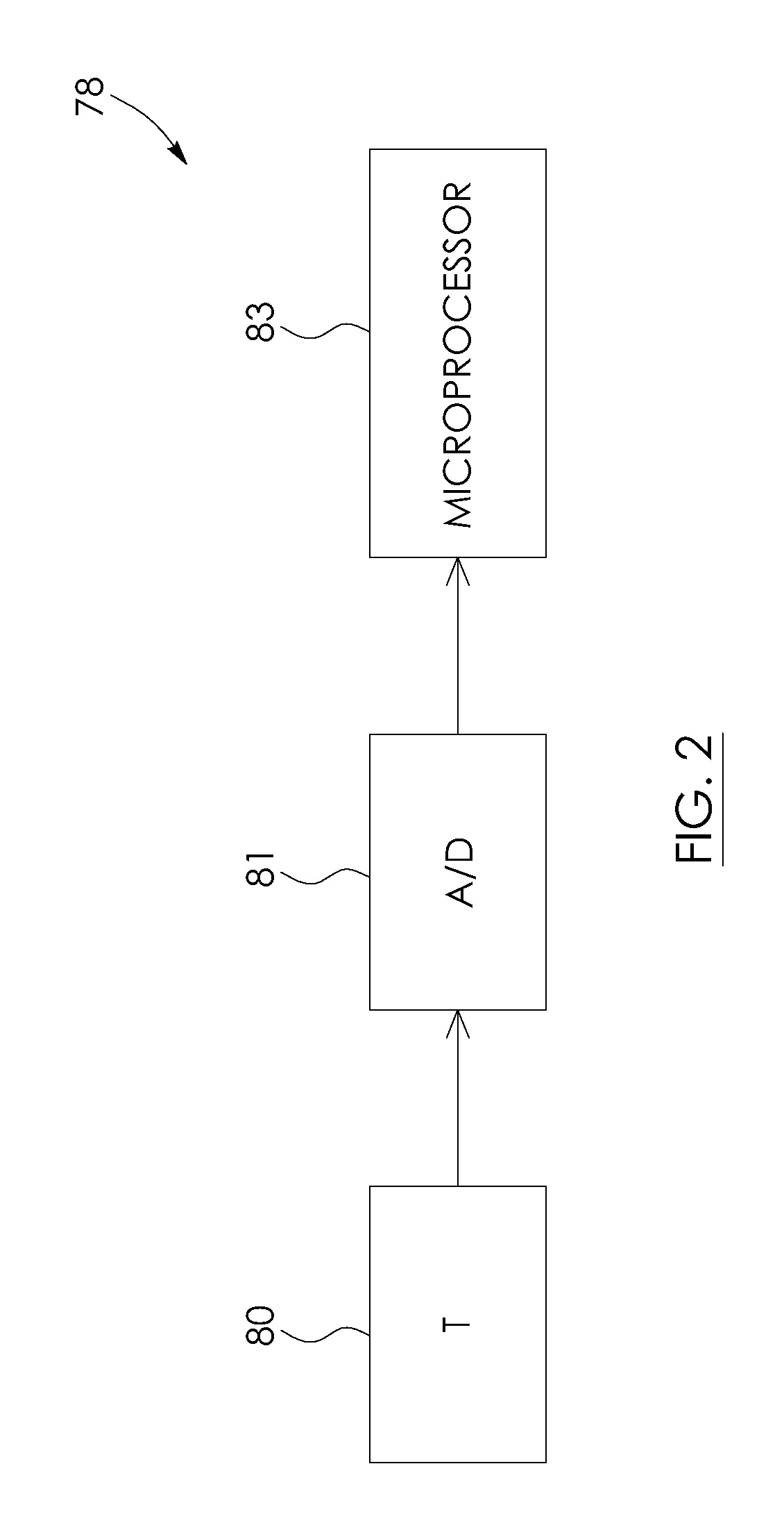
[0048]In operation, as arms 28 are angularly displaced, switch 86 sends a signal to the computer 85.1 at every increment at which cylinder 70, in this example, spans an angle equal to the angle α. The computer 85.1 is programmed such that, upon receiving the signal from the switch 86, it records the output ...

third embodiment

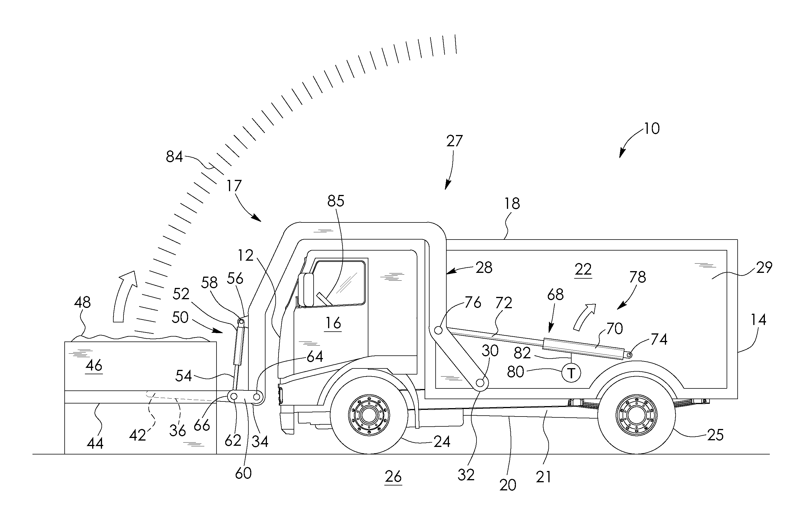
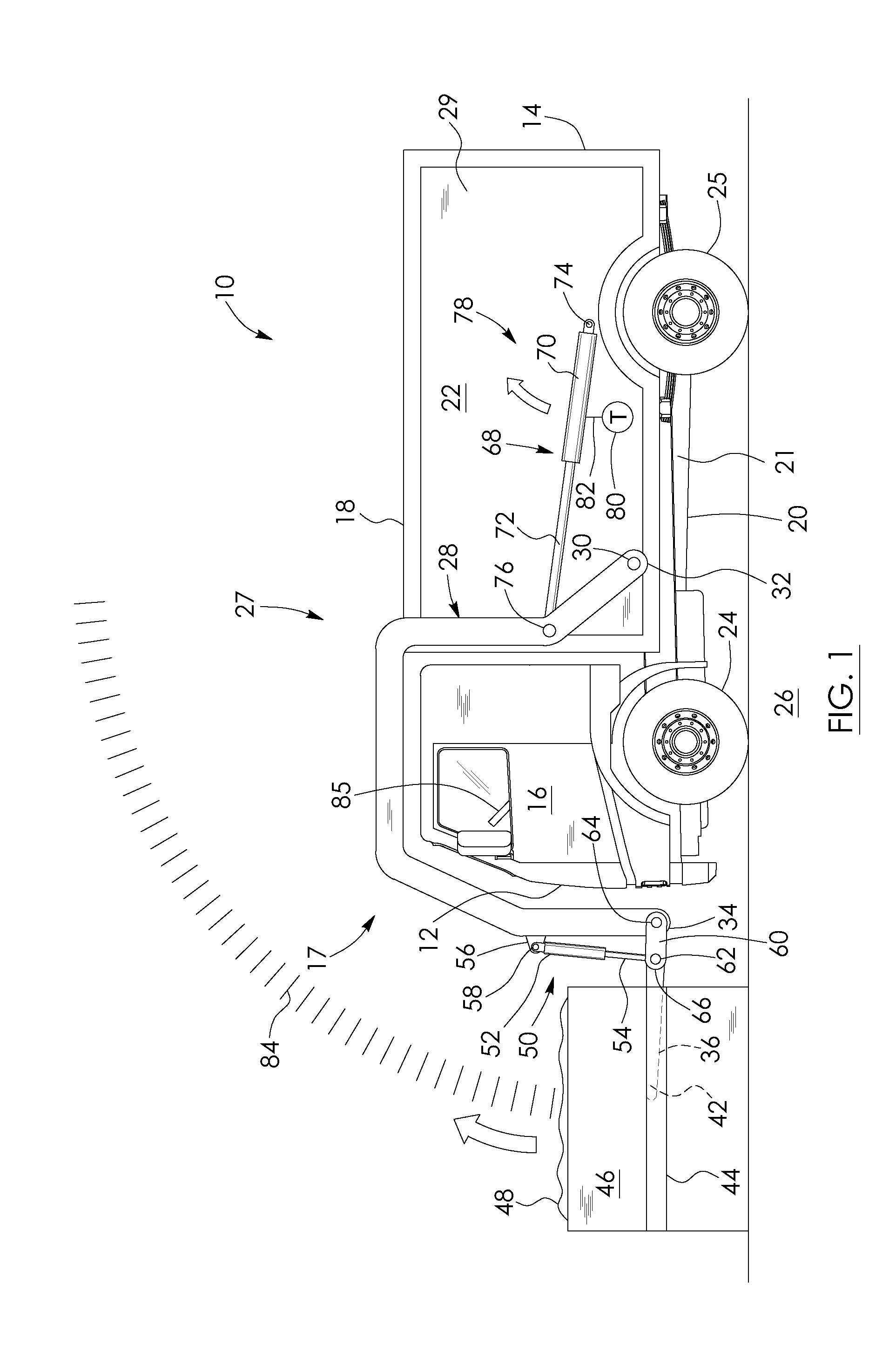
[0051]FIGS. 5 to 8 show the vehicle 10 of FIG. 1 together with a load measuring system 78.2 specifically adapted for garbage trucks. Like parts of system 78.2 have like numbers and functionings as system 78 with the addition of the numeral extension “0.2”. The load measuring system shown in FIGS. 5 to 8 is substantially similar to that shown in FIGS. 1, 3 and 4 with the exception that, instead of an angle sensor, system 78.2 has a button 88 disposed within the cab 16 and in communication with the computer 85.2. The button sends out a signal upon the button being actuated. The computer is programmed such that, upon receiving the signal from the button, it records the output of the transducer 80.2.

[0052]There are five stages for the operator of the garbage truck to follow for system 78.2. Referring to FIG. 5, the first stage is where the waste disposal vehicle 10 has its arms 28 and forks 36 lowered in preparation for picking up a waste load but where the forks are unloaded, free of ...

fourth embodiment

[0059]FIGS. 9 and 10 show the vehicle 10 shown in FIG. 1 together with a load weighing system 78.3 according to a Like parts of system 78.3 have like numbers and functionings as the embodiment shown in FIG. 1 with the addition of “0.3”. System 78.3 is substantially the same as system 78 shown in FIG. 1 with the exception that, instead of hydraulic transducers, system 78.3 has a plurality of load cells in communication with the computer 85.3, including a pair of load cells 90 connected to the pair of forks 36, respectively, adjacent to ends 38 of the forks, and a plurality of load cells 92 connected to respective corners 94 of the frame 21 of the vehicle. The load cells are schematically in FIG. 9. The load cells 90 and 92 per se are conventional, off-the-shelf components well known to those skilled in the art and therefore their parts and operation per se will not be described in detail. Load cells 90 and 92 are configured to output electrical signals, in this example signals, that...


PUM


Abstract

There is provided a system for monitoring payload for a load-lifting vehicle. The vehicle has a lifting arm and a hydraulic actuator operatively connected to the lifting arm. The system has a means for correlating actuator pressure within the actuator at a set position of the lifting arm with weight for generating a calculated weight of a payload. The system has a means for generating a payload pattern relating actuator pressure to time as the lifting arm moves the payload through a load cycle. The system has a means for comparing the payload pattern with a set pattern relating pressure to time corresponding to said calculated weight of the payload and storing the calculated weight of the payload into memory if the deviation between the patterns is equal to or less than a certain amount.

Description

CROSS REFERENCE TO RELATED APPLICATION[0001]This application claims the benefit of provisional application No. 61 / 485,866 filed in the United States Patent and Trademark Office on May 13, 2011, the disclosure of which is incorporated herein by reference and priority to which is claimed.FIELD OF THE INVENTION[0002]The present invention relates to a load-measuring, fleet asset tracking and data management system. In particular, the invention relates to a load-measuring, fleet asset tracking and data management system for load-lifting vehicles and shipping container loaders.DESCRIPTION OF THE RELATED ART[0003]U.S. Pat. No. 4,919,222 to Kyrtsos et al. discloses a dynamic payload monitor for measuring and displaying a payload weight for a loader vehicle. It does so by sensing the hydraulic pressure and position of the lifting arm cylinders. The system includes a calibration step where the operator moves an empty loader bucket through a load cycle. The monitor has a load cycle reset contr...

Claims


Application Information

Patent Timeline
IPC IPC(8): G01G19/10
CPCG01G19/10E02F3/342B65F3/046B65F2003/022B65F2003/0279E02F9/264
Inventor EPPERT, DAVID AARON
Owner DEPLOY TECH
Why Eureka
Try Eureka