Method and device for application of liquid polymeric material onto spinning cords

a technology of liquid polymeric material and spinning cord, which is applied in the direction of filament/thread forming, auxillary shaping apparatus, manufacturing tools, etc., can solve the problems of difficult regulation, clogging of capillaries, and the application of polymeric material onto the active zone of the cord from the bottom side of the cord does not always guarantee the same effect, so as to eliminate or at least reduce the disadvantages of background ar

Active Publication Date: 2014-03-06
ELMARCO SRO
View PDF1 Cites 6 Cited by
  • Summary
  • Abstract
  • Description
  • Claims
  • Application Information

AI Technical Summary

Benefits of technology

[0007]The technique according to the invention prevents evaporation of solvent from the liquid polymeric material during application on the cord and so ageing of the liquid polymeric material is slowed down. The spinning process runs after the cord leaves the application means and only from the layer stuck on the cord, which improves uniformity of produced nanofibres.
[0012]To secure continuous supply of the liquid polymeric material for long-time maintaining the spinning process, the supply chamber is connected with the reservoir of the liquid polymeric material which is formed by the working reservoir of fresh liquid polymeric material.
[0015]To secure stable supply of the liquid polymeric material, especially during long-term operation it is advantageous if there is the dosing device of the liquid polymeric material arranged between the reservoir or the working reservoir of the liquid polymeric material and the application means or number of application means.
[0016]With respect to the fact that there is very small amount of the liquid polymeric material needed to supply to the application means, it is advantageous if the dosing device is equipped with a pump capable of supplying with the liquid polymeric material in small separate doses or continuously in small amount.
[0021]In terms of quality of the applied layer, it is advantageous for all embodiments, if the cord meets the axis of the application holes.

Problems solved by technology

A disadvantage of the capillary application means is possibility of clogging-up of the capillaries, especially with the drying out and ageing liquid polymeric material, which is in contact with air.
Another disadvantage of the capillary application means is that it is difficult to regulate it, especially with respect to polymer consumption.
Application of Polymeric material onto the active zone of the cord from the bottom side of the cord does not always guarantee the same and uniform polymeric material layer on the top side of the spinning cord.
The disadvantage of this arrangement is the fact that in case of most of polymeric materials the spinning effect probably occurs also on the roller surface off the cords.
Another disadvantage is free level of polymer in the reservoir from which solvent evaporates, which even in case of mixing results in faster ageing of the polymeric material mixing.

Method used


Image

  • Method and device for application of liquid polymeric material onto spinning cords
  • Method and device for application of liquid polymeric material onto spinning cords
  • Method and device for application of liquid polymeric material onto spinning cords

Examples


Embodiment Construction

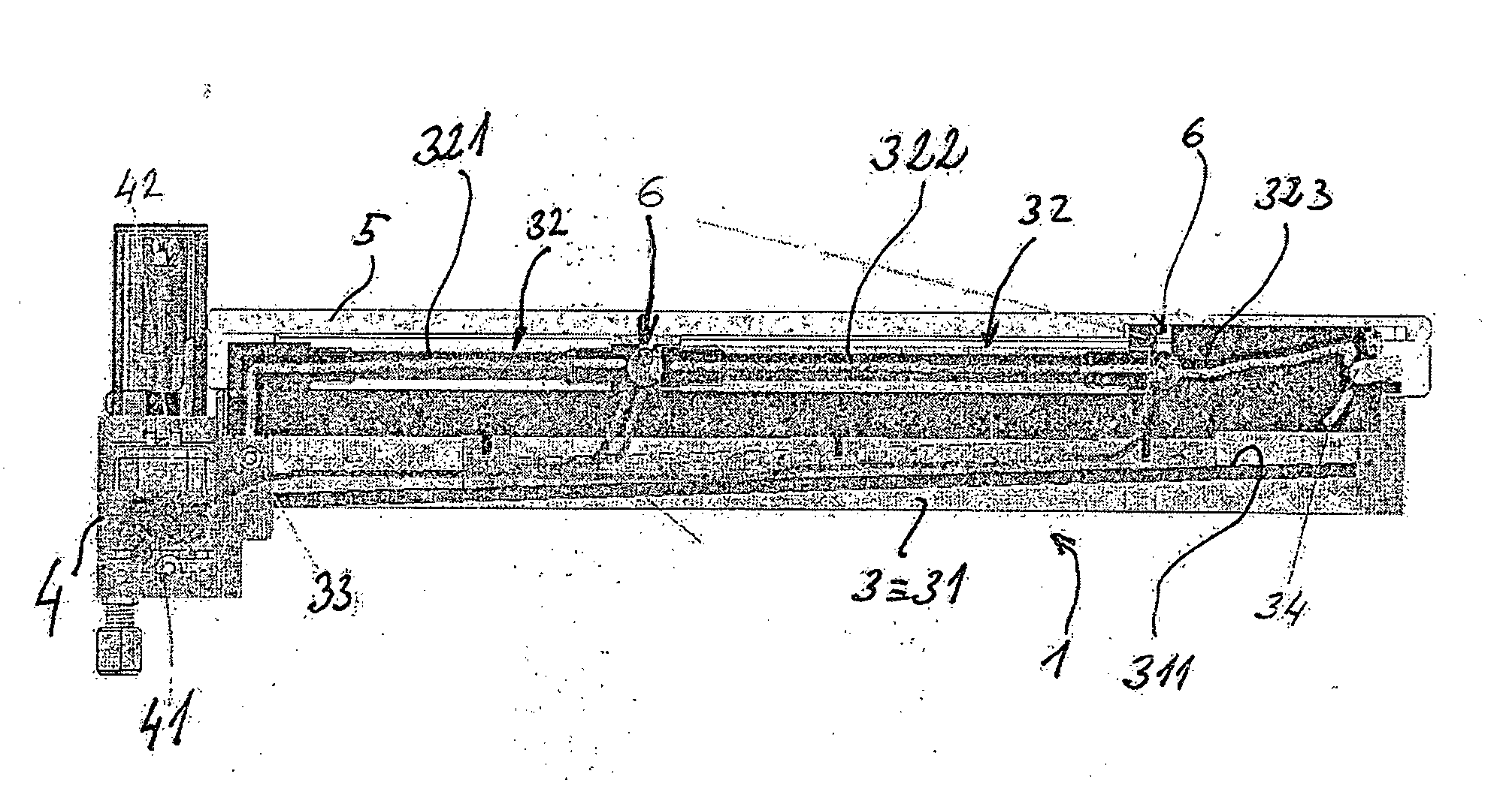
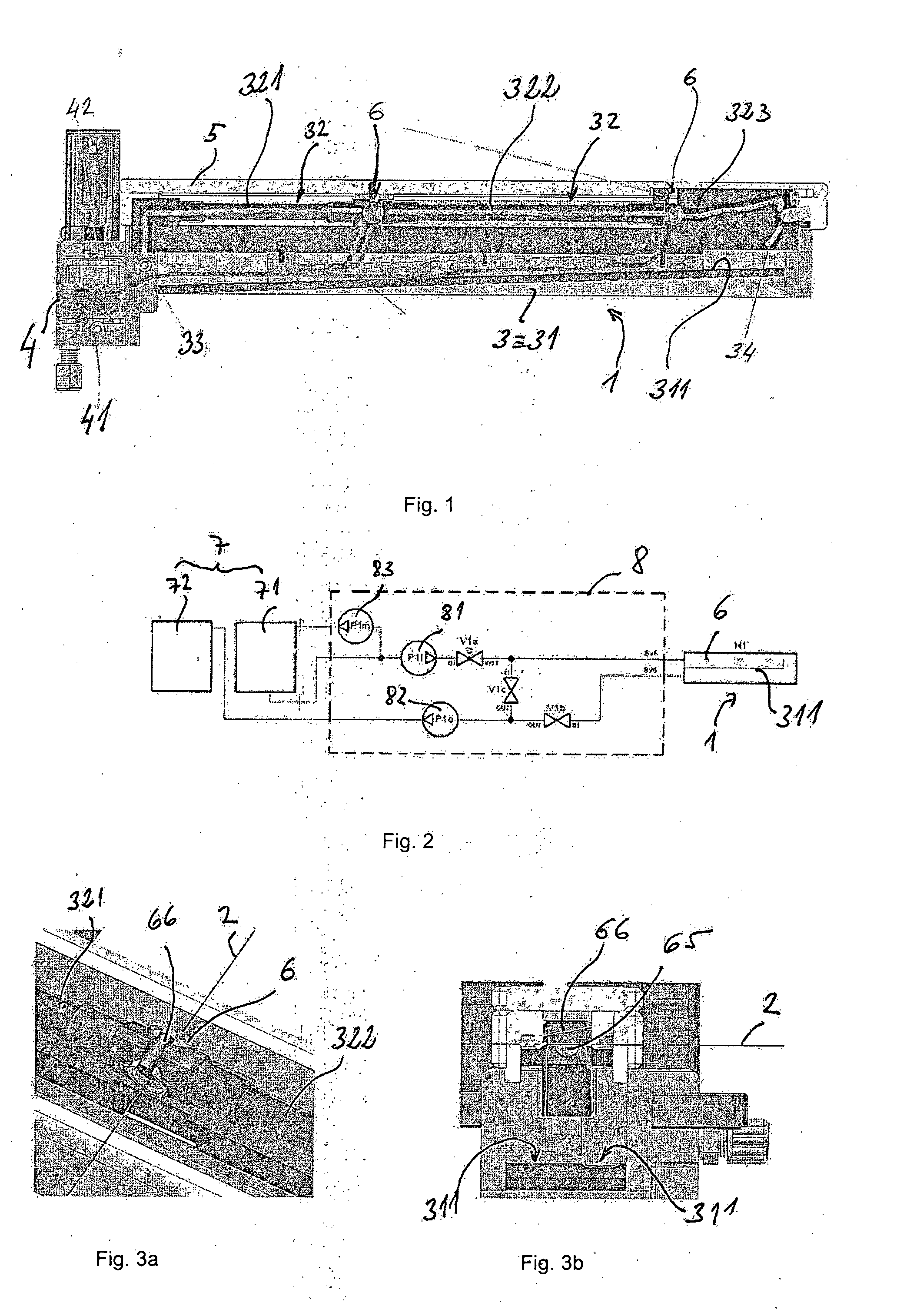
[0032]The device for application of the liquid polymeric material on the active spinning zone of the cord of the spinning member of the spinning electrode according to the invention in the example of embodiment shown in the FIG. 1, 3a, 3b comprises the carrying body 1 common for two cords 2 of the spinning member of the spinning electrode created for example according the EP 2173930 (WO 2009 / 010020). The carrying body 1 is mounted reversibly displaceably along the active spinning zone of both cords 2 and its main part is the tank 3, which is firmly mounted on the base body 4 and equipped at the upper section with the removable cover 5. The tank 3 is arranged perpendicularly to the cords 2 and is formed by a hollow body 31 opened from above, which has an inclined bottom 311 sloped down to the base body 4. In the cavity of the tank 3 there is arranged a system of tubes 32 whose beginning is connected to an inlet 33 of the liquid polymeric material, which is in the shown embodiment arr...


PUM

PropertyMeasurementUnit
thicknessaaaaaaaaaa
distanceaaaaaaaaaa
diameteraaaaaaaaaa

Abstract

The present disclosure relates to a method and a device for application of liquid polymeric material onto the active spinning zone of the cord of the spinning member of the spinning electrode, where the application means moving reversibly along the active spinning zone of the cord in the device for production of nanofibres through electrostatic spinning of liquid material in electrostatic field of high intensity between at least one spinning electrode and against it arranged collecting electrode. The liquid polymeric material is applied onto the cord around its whole circumference without any contact with gaseous environment in the spinning space, where the application means reversibly moves, whereas while the cord is leaving the application means the thickness of the layer of the liquid polymeric material is being reduced and immediately after leaving the application means the process of electrostatic spinning of the liquid polymeric material applied on the cord is started.

Description

CROSS-REFERENCE TO RELATED APPLICATIONS[0001]The present application is a 35 U.S.C. §371 National Phase conversion of PCT / CZ2012 / 000019, filed Feb. 27, 2012, which claims benefit of Czech Republic Application No. PV 2011-212, filed Apr. 12, 2011, the disclosure of which is incorporated herein by reference. The PCT International Application was published in the English language.TECHNICAL FIELD[0002]The invention relates to a method for application of liquid polymeric material onto active spinning zone of a cord of spinning member of spinning electrode byan application means moving reversibly along the active spinning zone of the cord in a device for production of nanofibres through electrostatic spinning of liquid material in electrostatic field of high intensity between at least one spinning electrode and against it arranged collecting electrode.[0003]Further the invention relates to a device for application of liquid polymeric material onto active spinning zone of a cord of a spinn...

Claims


Application Information

Patent Timeline
Patent Type & Authority Applications(United States)
IPC IPC(8): D01D5/00
CPCD01D5/0069D01D5/003D01D5/00
Inventor MALY, MIROSLAVSEJAK, PAVELSTROMSKY, VITNYDRLE, MILANBITTNER, MICHALMARES, LADISLAVCMELIK, JANHANUSOVA, LENKAPODANY, MARTINKRENEK, RADIM
Owner ELMARCO SRO
Why Eureka
Try Eureka