Contactless power transfer system

a power transfer system and contactless technology, applied in the direction of charging stations, electric devices, transportation and packaging, etc., can solve the problems of significant decrease in the efficiency and power transfer capabilities of the three coil systems

Active Publication Date: 2014-03-06
GENERAL ELECTRIC CO
View PDF12 Cites 17 Cited by
  • Summary
  • Abstract
  • Description
  • Claims
  • Application Information

AI Technical Summary

Benefits of technology

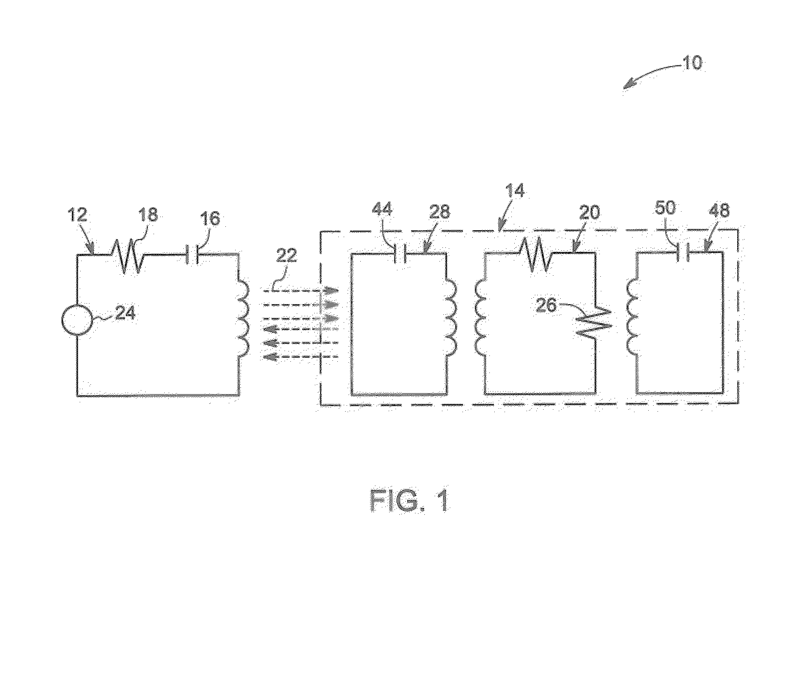
[0006]Briefly, in accordance with an embodiment, a contact less power transfer system is provided. The system includes a power exchanging coil configured to exchange power via a magnetic field. The system also includes a field focusing element for focusing the magnetic field. The system further includes a compensation coil having a resonance frequency different from a resonance frequency of the field focusing element for matching an impedance of the contactless power transfer system and compensating a change in phase resulting from a misalignment in the contactless power transfer system.

Problems solved by technology

In addition, small misalignment between the transmitter coil and the receiver coil results in significant decrease in the efficiency and power transfer capabilities of the three coil systems.

Method used


Image

  • Contactless power transfer system
  • Contactless power transfer system
  • Contactless power transfer system

Examples


Embodiment Construction

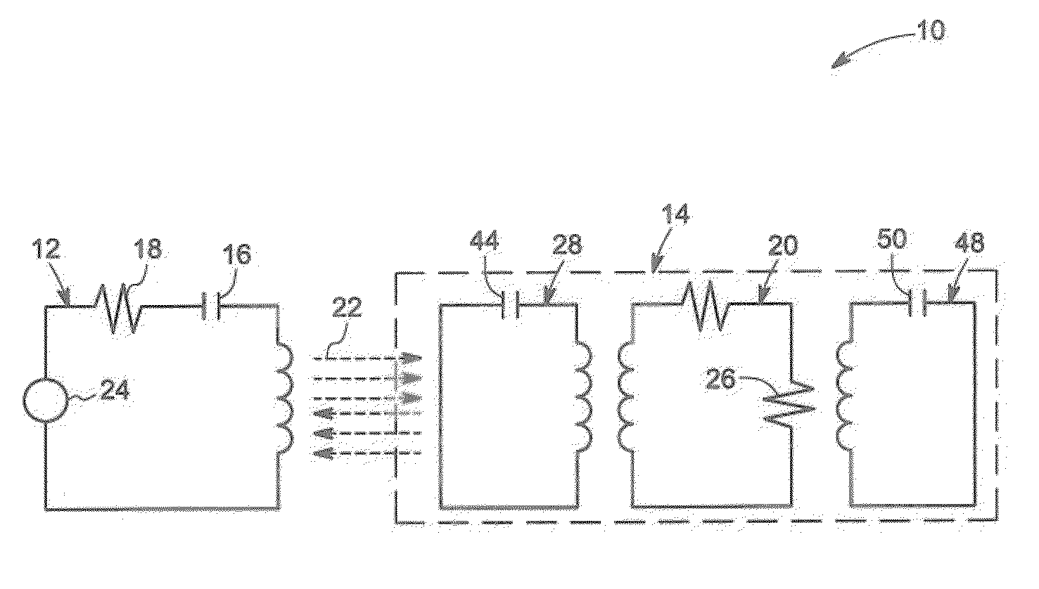
[0021]Embodiments of the present invention include a system and method for contactless power transfer. The system includes a power exchanging coil that exchanges power via a magnetic field. The system also includes a field focusing element that focuses the magnetic field onto the power exchanging coil. The system further includes a compensation coil that matches an impedance of the contactless power transfer system and also compensates for a change in phase resulting from a misalignment in the contactless power transfer system. The contactless power transfer system will be described in greater detail with respect to FIG. 1 below.

[0022]Unless defined otherwise, technical and scientific terms used herein have the same meaning as is commonly understood by one of ordinary skill in the art to which this disclosure belongs. The terms “first”, “second”, and the like, as used herein do not denote any order, quantity, or importance, but rather are used to distinguish one element from another...


PUM

PropertyMeasurementUnit
magnetic fieldaaaaaaaaaa
resonance frequencyaaaaaaaaaa
impedanceaaaaaaaaaa

Abstract

A contactless power transfer system comprising a power exchanging coil configured to exchange power via a magnetic field, a field focusing element for focusing the magnetic field, and a compensation coil having a resonance frequency different from a resonance frequency of the field focusing element for matching an impedance of the contactless power transfer system and compensating a change in phase resulting from a misalignment in the contactless power transfer system.

Description

BACKGROUND OF THE INVENTION[0001]Embodiments of the present invention generally relate to power transfer systems and, more particularly, to contactless power transfer systems.[0002]Power transfer systems are employed for transmitting power from one object to another. Based on a method of transmitting power, the power transfer systems can be classified into power transfer systems using physical connections between a transmitter and a receiver for transmitting power and contactless power transfer systems in which there is no physical connection between the transmitter and the receiver.[0003]The contactless power transfer systems employ various methods for transmitting power wirelessly. One such approach is an inductive coupling system that includes a transmitter coil and a receiver coil in which both are inductively coupled to a respective transformer winding and transmit power based on inductive coupling.[0004]In an alternative approach, a resonator based contactless power transfer s...

Claims


Application Information

Patent Timeline
Patent Type & Authority Applications(United States)
IPC IPC(8): H01F38/14
CPCH01F38/14Y02T90/14Y02T10/7072B60L53/12B60L53/31B60L53/36Y02T10/70Y02T90/12H02J50/402H02J50/90H02J50/12
Inventor BOHORI, ADNAN KUTUBUDDINBHAT, SUMA MEMANA NARAYANARAGHUNATHAN, ARUN KUMAR
Owner GENERAL ELECTRIC CO
Why Eureka
Try Eureka