Vibration generation device

Inactive Publication Date: 2014-03-06
MPLUS
View PDF7 Cites 22 Cited by
  • Summary
  • Abstract
  • Description
  • Claims
  • Application Information

AI Technical Summary

Benefits of technology

[0013]An aspect of the present invention provides a smaller linear vibrator

Problems solved by technology

Second, the vibration generation device needs to have a rapid response speed, keeping pace with the speed of a user touching a touchscreen.
However, since the linear vibrator includes some essential components, limitations exist on the miniaturization of the linear vibrator.
Further, the linear vibrator gener

Method used


Image

  • Vibration generation device
  • Vibration generation device
  • Vibration generation device

Examples


Embodiment Construction

[0034]Hereinafter, embodiments of the present invention will be described in detail with reference to the accompanying drawings. The invention may, however, be embodied in many different forms and should not be construed as being limited to the embodiments set forth herein. Rather, these embodiments are provided so that this disclosure will be thorough and complete, and will fully convey the scope of the invention to those skilled in the art. In the drawings, the shapes and dimensions of elements may be exaggerated for clarity, and the same reference numerals will be used throughout to designate the same or like elements.

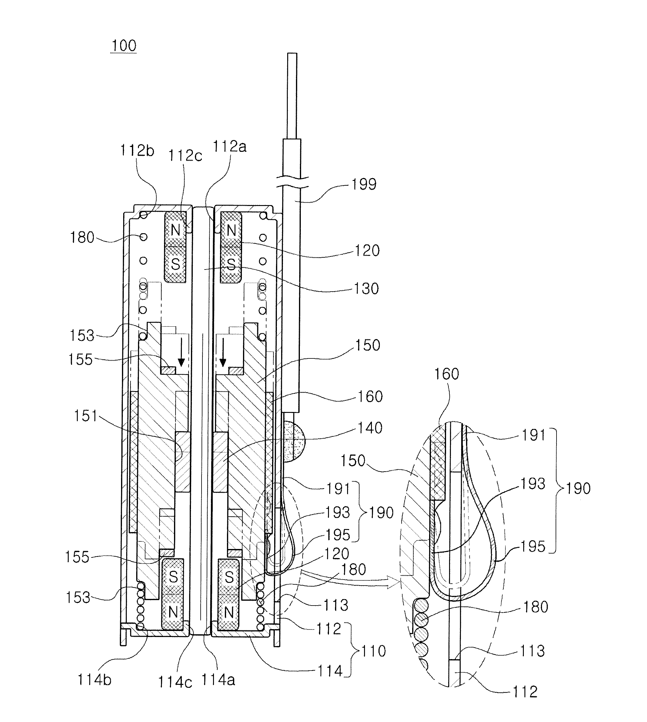
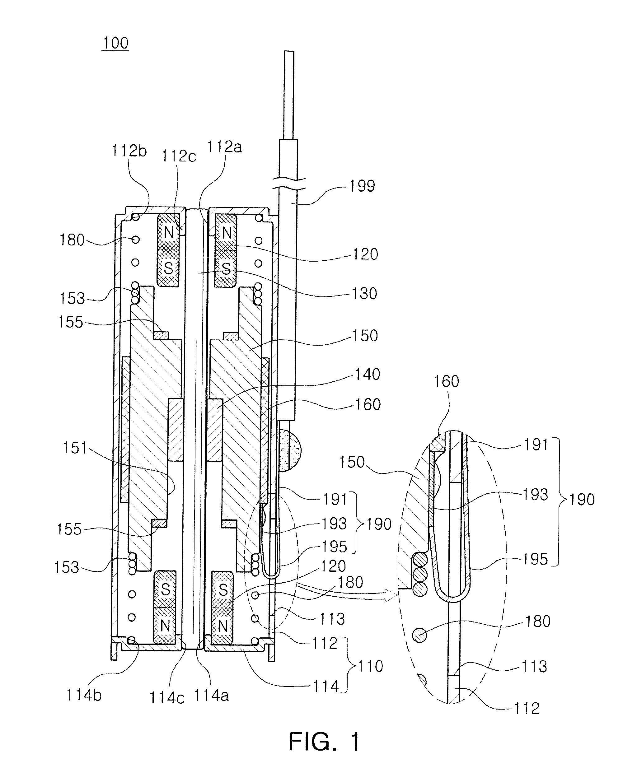
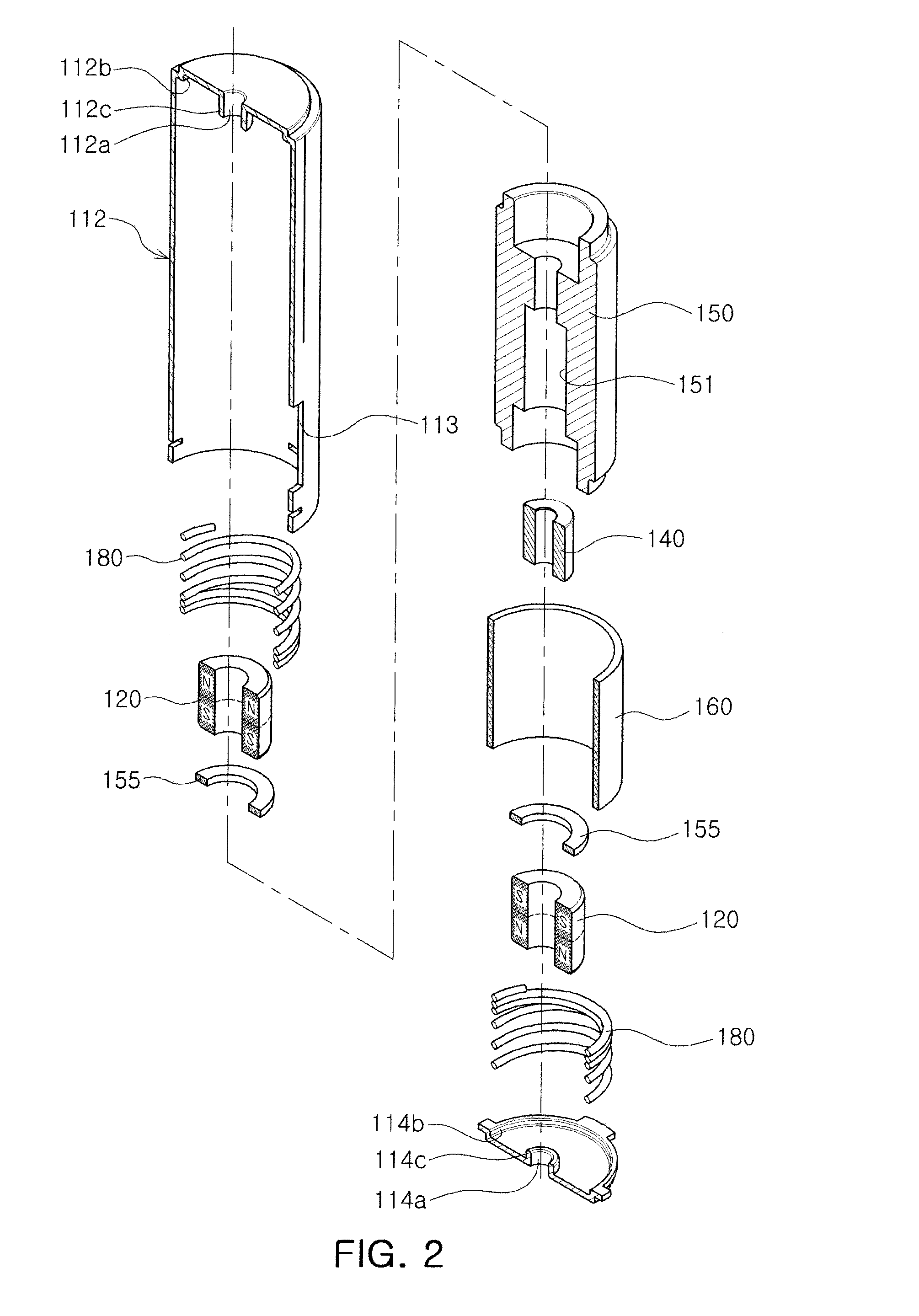
[0035]FIG. 1 is a combined cross-sectional view of a vibration generation device according to an embodiment of the present invention, FIG. 2 is a partially cut-away exploded perspective view of the vibration generation device according to the embodiment of the present invention, and FIGS. 3A and 3B are reference diagrams illustrating a form of vibrations of the vibr...


PUM


Abstract

There is provided a vibration generation device, including: a housing including an internal space; a shaft passing through the internal space in an axial direction and mounted in the housing; a bearing member vibrated in the axial direction while contacting the shaft; a yoke mounted on the bearing member; a coil mounted on an outer surface of the yoke; a magnet interacting with electromagnetic force exerted on the yoke by the coil and included in the internal space; and at least one elastic member connected between an end of the yoke in the axial direction and a surface of the housing in the axial direction.

Description

CROSS-REFERENCE TO RELATED APPLICATIONS[0001]This application claims the priority of Korean Patent Application No. 10-2012-0098830 filed on Sep. 6, 2012, in the Korean Intellectual Property Office, the disclosure of which is incorporated herein by reference.BACKGROUND OF THE INVENTION[0002]1. Field of the Invention[0003]The present invention relates to a vibration generation device.[0004]2. Description of the Related Art[0005]A vibration generation device, a component converting electrical energy into mechanical vibrations using a principle of generation of electromagnetic force, is mounted in cellular phones, and the like, to be used for silently informing a user of call receipt.[0006]Further, there is a growing demand for a multi-functional cellular phones as the market for portable electronic devices such as cellular phones, and the like, rapidly expands. Since demand for small, high-quality electronic device components is also increasing, demand for development of a vibration ge...

Claims


Application Information

Patent Timeline
IPC IPC(8): H02K33/00
CPCH02K33/00H02K33/18H02K33/02
Inventor KIM, YONG TAEHONG, JR., JUNG TAEKPARK, KYUNG SUMOON, DONG SU
Owner MPLUS
Why Eureka
Try Eureka