LED drive circuit

a technology of led drive circuit and led bulb, which is applied in the direction of electric variable regulation, process and machine control, instruments, etc., can solve the problems of large power consumption of the drive ic circuit, the difficulty of fitting the led drive circuit with a large number of parts in a limited space of the led bulb, and the number of parts configuring the led drive circui

Active Publication Date: 2014-03-06
FUJI ELECTRIC CO LTD
View PDF5 Cites 26 Cited by
  • Summary
  • Abstract
  • Description
  • Claims
  • Application Information

AI Technical Summary

Problems solved by technology

However, with regard to an LED bulb, it is necessary to fit the LED drive circuit, as well as the LED main body, in a bulb of the same size as a heretofore known incandescent bulb, and it is in general difficult to fit the LED drive circuit with a large number of parts in a limited space of the LED bulb, meaning that it is important to reduce the number of parts configuring the LED drive circuit.
Also, as an arrangement is such that an operating current

Method used


Image

  • LED drive circuit
  • LED drive circuit
  • LED drive circuit

Examples


first embodiment

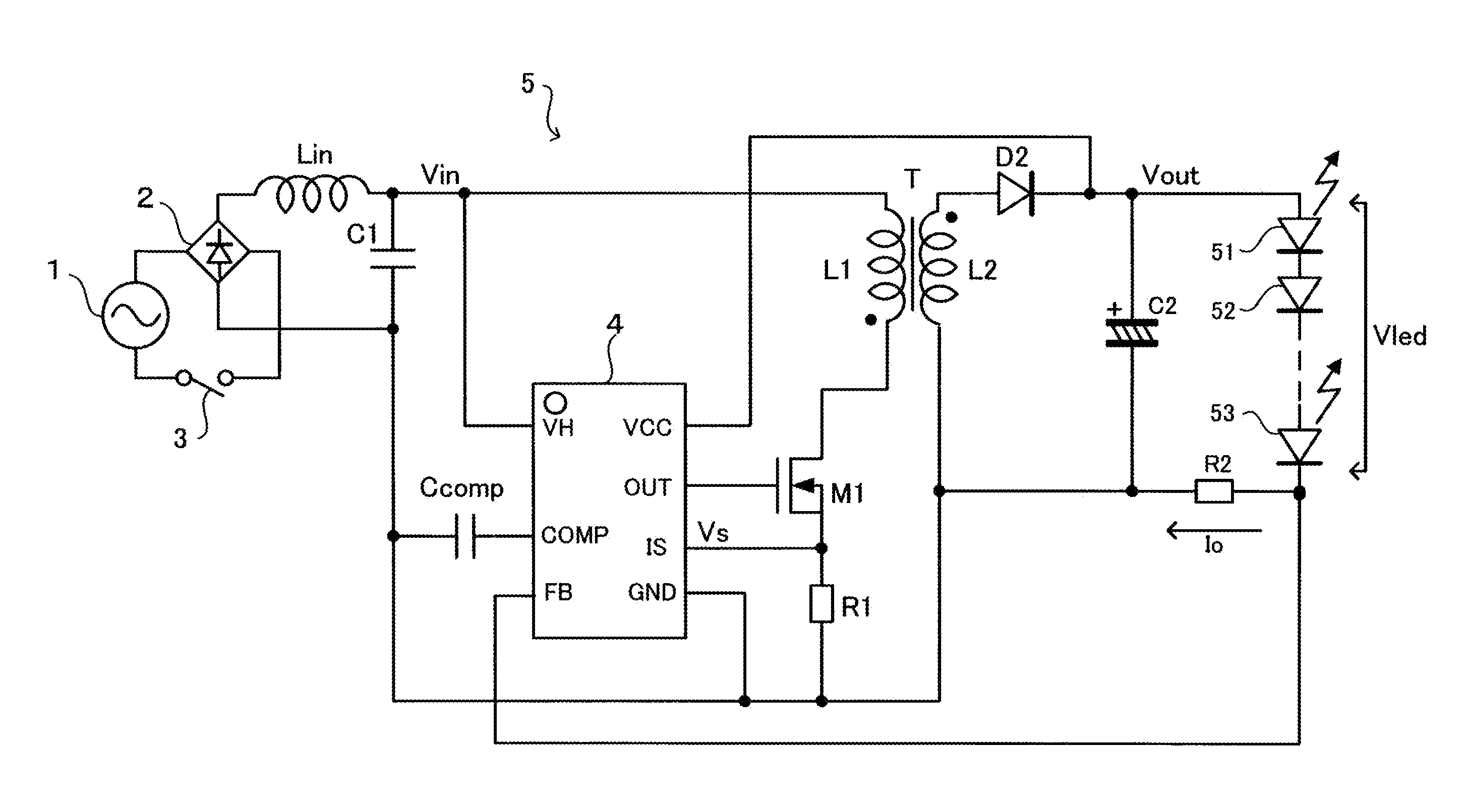
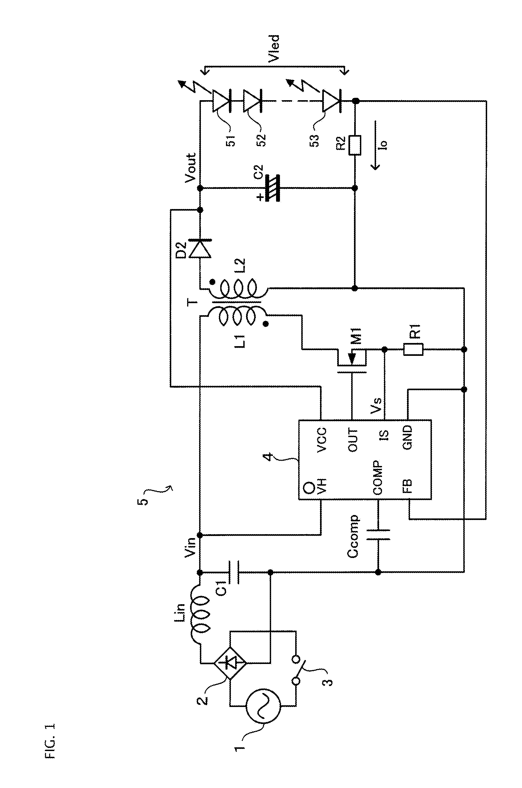
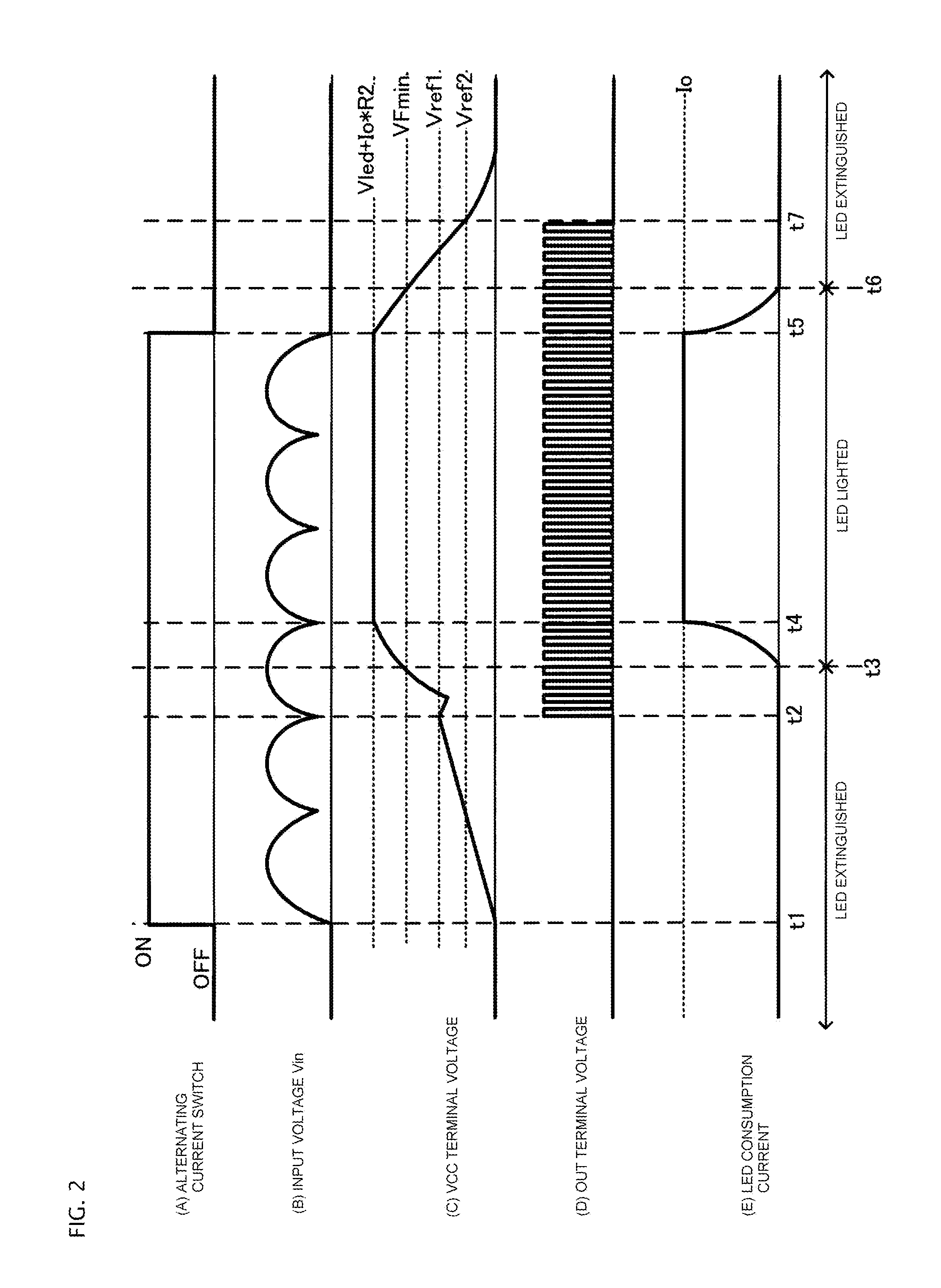
[0042]FIG. 1 is a diagram showing an LED drive circuit according to the invention. Herein, circuit components corresponding to those of a heretofore known flyback converter configuration LED drive circuit shown in FIG. 6 are given the same reference numerals and signs, and a description thereof is omitted.

[0043]The LED drive circuit 5, in order to control a plurality of LEDs 51 to 53 connected in series to be constant, is configured in such a way that the ground side of a primary side circuit and secondary side circuit of a transformer T is short-circuited, and a voltage signal at a connection point of a current sensing resistor R2 with the cathode electrode of the LED 53 is fed back to an FB terminal 44 of a drive IC circuit 4.

[0044]The drive IC circuit 4 is made to have the previously described internal circuit configuration shown in FIG. 7, and a VCC terminal 41 of the drive IC circuit 4 is connected to one end of a smoothing capacitor C2 provided on the secondary side of the tra...

second embodiment

[0063]FIG. 5 shows an LED drive circuit 6 according to the invention. Herein too, circuit components corresponding to those of the heretofore known flyback converter configuration LED drive circuit shown in FIG. 6 are given the same reference numerals and signs, and a description thereof is omitted.

[0064]In the LED drive circuit 6, a drive IC circuit without a built-in high-voltage start-up circuit 10 (refer to FIG. 7) is used as the drive IC circuit 7. Because of this, an arrangement is such that a starting current to be supplied to the smoothing capacitor C2 on the secondary side of the transformer T when the alternating current switch 3 is turned on is supplied from a starting resistor Rst provided as a current supply circuit between the smoothing capacitor C2 and the Vin on the primary side.

[0065]With the LED drive circuit 6 of the second embodiment, in order to carry out a stable constant voltage control of the LEDs 51 to 53 with the drive IC circuit 7, it is desirable to set a...


PUM


Abstract

In aspects of the invention, a flyback converter configuration LED drive circuit, by adopting a configuration such that anode voltages of LEDs smoothed by a smoothing capacitor on the secondary side of a transformer and a terminal of a drive IC circuit are used as a node common. Current can be supplied to the primary side of the smoothing capacitor by a start-up circuit when starting, the need for an auxiliary winding, smoothing capacitor, and rectifier diode which have heretofore been necessary to supply a power source to the drive IC circuit is eliminated. Consequently, the number of parts can be reduced, meaning that the configuration of the LED drive circuit becomes simple, thus enabling a reduction in size and cost of the LED drive circuit.

Description

CROSS-REFERENCE TO RELATED APPLICATIONS[0001]This application is a continuation of International Application No. PCT / JP2012 / 052839, filed on Feb. 8, 2012, which is based on and claims priority to Japanese Patent Application No. JP 2011-129336, filed on Jun. 9, 2011. The disclosure of the Japanese priority application and the PCT application in their entirety, including the drawings, claims, and the specification thereof, are incorporated herein by reference.BACKGROUND[0002]1. Field of the Invention[0003]Embodiments of the invention relates to an LED drive circuit which converts an alternating current commercial power source to a direct current voltage necessary to cause light emitting diodes (hereafter referred to as “LEDs”) to emit light, and controls lighting of the LEDs, and particularly, relates to an LED drive circuit wherein the need for an auxiliary winding of a transformer, a current limiting resistor thereof, a rectifier diode, a smoothing capacitor, or the like, which has ...

Claims


Application Information

Patent Timeline
IPC IPC(8): H05B37/02H05B44/00
CPCH05B37/02H02M1/36H02M3/33507H05B45/10H05B47/10H05B45/385H02M1/0006
Inventor SONOBE, KOJI
Owner FUJI ELECTRIC CO LTD
Why Eureka
Try Eureka