Power supply, power supply charging circuit and method and terminal equipment

A charging method and charging circuit technology, applied in the field of power supply, can solve the problems of prolonging the constant current charging time, low charging speed, and inaccurate time, and achieve the effects of prolonging the constant current charging time, reducing the charging time, and increasing the charging speed

Inactive Publication Date: 2014-04-23
XIAOMI INC
View PDF5 Cites 16 Cited by
  • Summary
  • Abstract
  • Description
  • Claims
  • Application Information

AI Technical Summary

Problems solved by technology

[0004] However, the power supply charging control circuit usually detects the positive pole voltage of the power supply. Due to the existence of protection components and protection circuits, the positive pole voltage of the power supply is higher than the positive pole voltage of the battery inside the power supply. Therefore, it is inaccurate to judge whether the voltage of the power supply reaches the threshold value. As a result, the timing of switching from the constant current mode to the constant voltage mode is inaccurate, and the constant current charging time cannot be extended to the greatest extent, so that the entire charging time of the power supply is prolonged and the charging speed is low.

Method used


Image

  • Power supply, power supply charging circuit and method and terminal equipment
  • Power supply, power supply charging circuit and method and terminal equipment
  • Power supply, power supply charging circuit and method and terminal equipment

Examples


Embodiment Construction

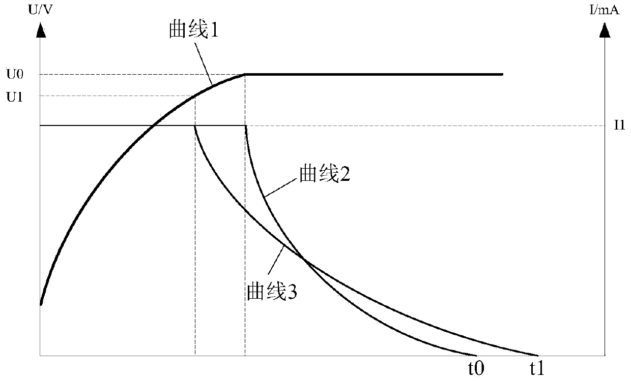
[0040] The power supply usually includes a battery cell and a protection circuit. The protection circuit is used to protect the charging and discharging process of the battery cell. The circuit where the cell is located achieves the purpose of protecting the cell. Because there is a certain voltage drop on the protection circuit, the voltage of the power supply is not equal to the voltage of the internal battery core. Therefore, when the power supply is in the charging state, when the voltage of the power supply reaches the preset voltage, the voltage of the battery core does not reach the preset voltage. Voltage.

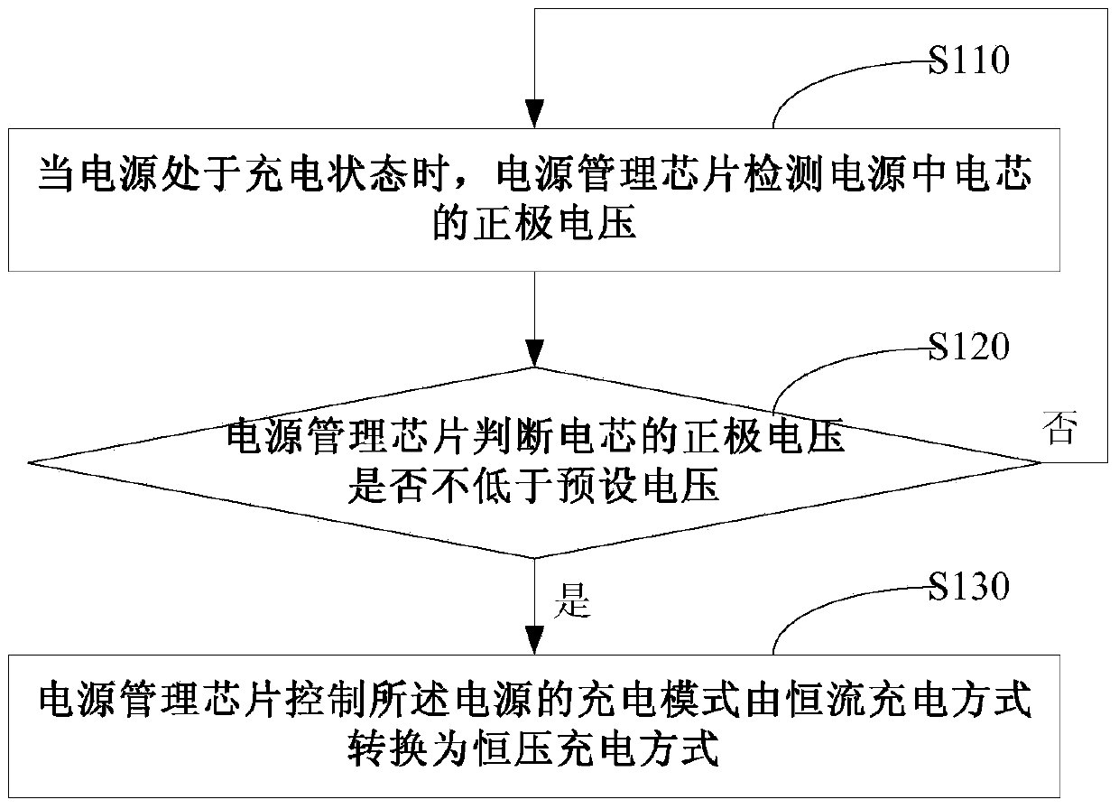
[0041] An embodiment of the present disclosure provides a charging method for a power supply. By detecting the voltage at both ends of the battery cell in the power supply, and when it is judged that the positive voltage of the battery cell is not lower than the preset voltage, the charging mode of the power supply is controlled to be constant current charging. The ...


PUM


Abstract

The embodiment of the invention discloses a power supply charging circuit and method, a power supply and terminal equipment. The power supply charging method comprises the following steps: when the power supply is under the charging state, a power supply management chip detects the anode voltage of a cell in the power supply; and when the anode voltage of the cell is detected to be not lower than a preset voltage, the power supply is controlled to be converted into a constant-voltage charging mode from a constant-current charging mode. Compared with the anode voltage charging mode of a detection power supply, the power supply charging method provided by the invention has the characteristics that the power supply charging mode is switched when the cell voltage is detected to achieve the preset voltage by the power supply management chip, so that the charging time of a constant-current charging mode can be prolonged to the maximum degree, the charging time of the constant-voltage charging mode is correspondingly shortened, the shortened constant-voltage charging mode time is more than the prolonged constant-current charging mode time, the integral charging time of the power supply is shortened, and the charging speed is improved.

Description

technical field [0001] The present disclosure relates to the field of power supply technology, in particular to a power supply charging circuit, method, power supply and terminal equipment. Background technique [0002] At present, the rechargeable power supply of terminal equipment usually includes a battery cell and a protection circuit. The battery cell is the power storage part of the rechargeable power supply, and the protection circuit is used to protect the charging and discharging process of the battery cell. [0003] For a single-cell rechargeable power supply (power supply including one battery cell), a constant current-constant voltage charging method is usually adopted, that is, a large current constant current method is used to charge first, and when the voltage of the power supply reaches the threshold value, it is converted into a charging current. Gradually decreasing constant voltage method, this charging method can fully extend the time of the constant curr...

Claims


Application Information

Patent Timeline
Patent Type & Authority Applications(China)
IPC IPC(8): H02J7/00
CPCH02J7/0029H02J7/00302H02J7/00304H02J7/0071H02J7/00714H02J7/00712Y02E60/10H01M10/446H01M10/44H02J7/00H02H7/18
Inventor 雷振飞孙伟郭迪凌
Owner XIAOMI INC
Why Eureka
Try Eureka