System and Method for Envelope Modulation

a technology of envelope modulation and system, applied in the field of communication satellites, can solve the problems of high slew rate, weight and power penalty, and achieve the effect of high power amplifier, and maintaining overall gain and efficiency

Active Publication Date: 2006-05-18
THE BOEING CO
View PDF3 Cites 16 Cited by
  • Summary
  • Abstract
  • Description
  • Claims
  • Application Information

AI Technical Summary

Benefits of technology

[0010] Another advantage of the present invention is that it provides a high power amplifier that is able to be externally controlled to maintain overall gain and efficiency, allowing the high power amplifier to be flexed over an RF output power dynamic range. In so doing, the present invention provides a high power amplifier that is capable of being used in multiple performance applications. By maintaining overall gain and efficiency, the present invention saves on power consumption.
[0011] Furthermore, the present invention reduces the amount of power consumed by a high power amplifier circuit by controlling the saturated output

Problems solved by technology

But, a high slew rate also comes a

Method used


Image

  • System and Method for Envelope Modulation
  • System and Method for Envelope Modulation
  • System and Method for Envelope Modulation

Examples


Embodiment Construction

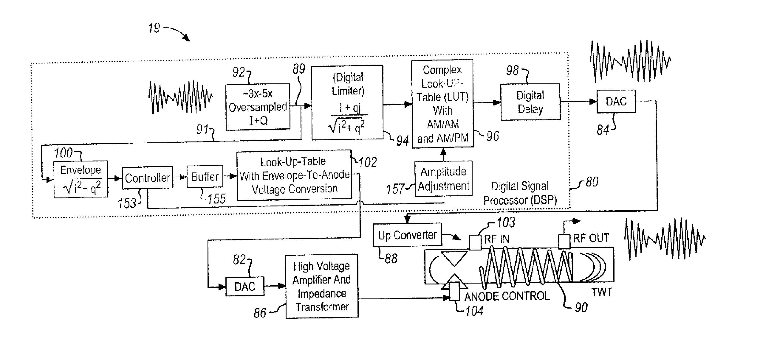
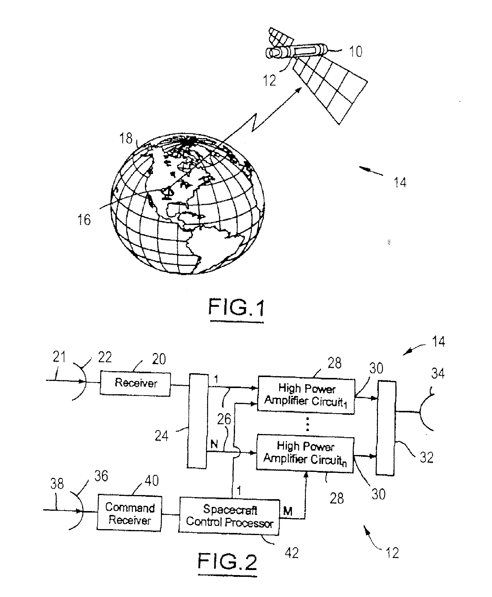
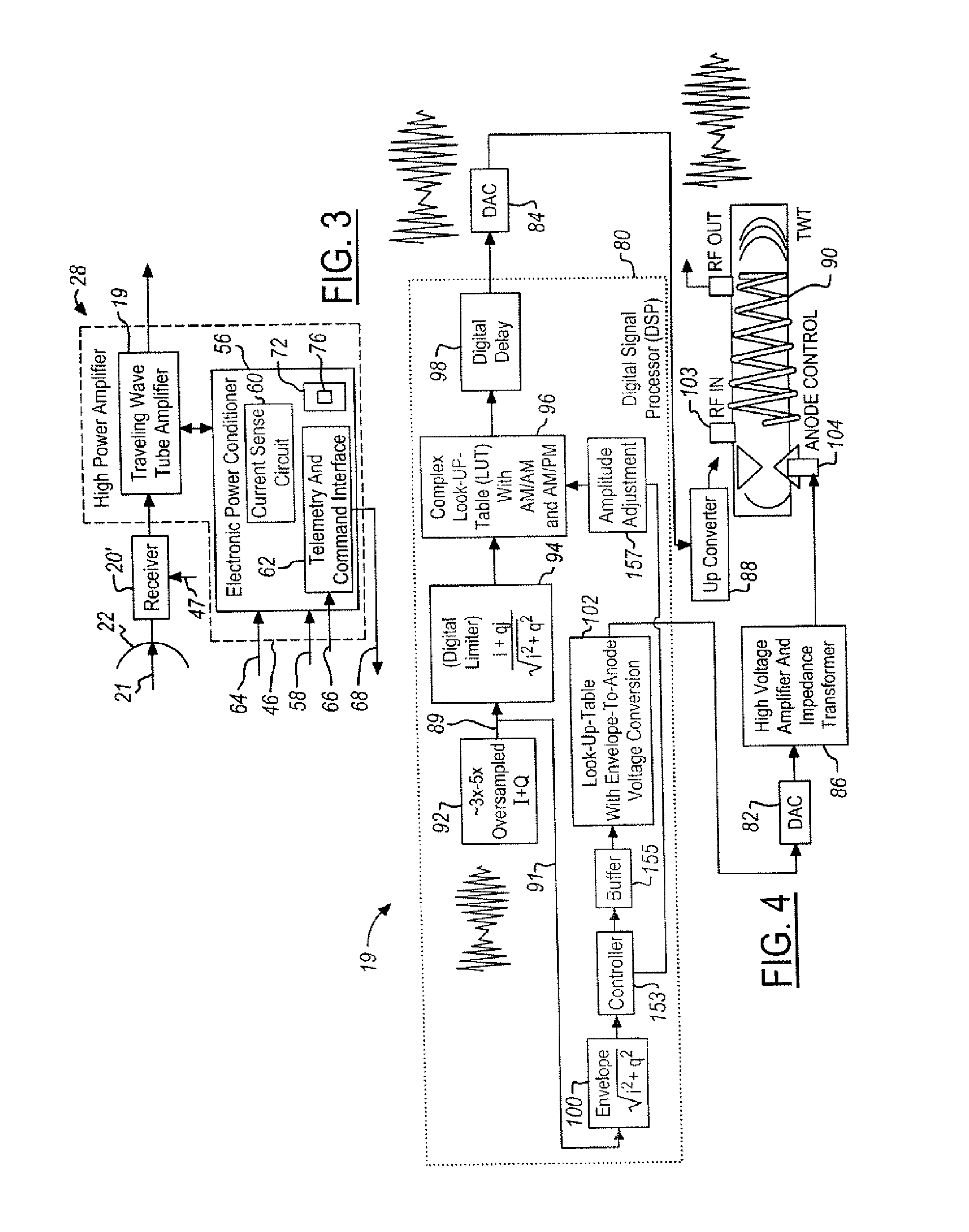
[0018] In the following figures the same reference numerals will be used to identify the same components. While the present invention is described with respect to a system and method of controlling saturated output power of a power control system for a satellite, the present invention may be adapted for various high power amplifier applications known in the art. It should be understood that the present invention is applicable to various types of high power amplifiers as well as various numbers of high power amplifiers. Also, the present invention may be employed in groups or rings of high power amplifiers.

[0019] In the following description, various operating parameters and components are described for one constructed embodiment. These specific parameters and components are included as examples and are not meant to be limiting.

[0020] The present invention is a method for performing modulation required to dynamically change the maximum output power of a traveling wave tube such tha...


PUM


Abstract

A power control system for a satellite receiving radio-frequency signals includes a digital processor and a traveling wave tube amplifier system and corresponding traveling wave tube. An anode voltage of the traveling wave tube amplifier system is used to modulate or saturate the current of the electron beam of the traveling wave tube so that the output power of the traveling wave tube amplifier system, from the saturated electron beam, is proportional to a waveform envelope of the radio-frequency signals. The digital processor controls anode and RF input signal amplitudes to the traveling wave tube and predicts necessary corrections.

Description

TECHNICAL FIELD [0001] The present invention relates generally to communication satellites, and more particularly, to a system and method of increasing power efficiency for such satellites. BACKGROUND ART [0002] Communication satellite payloads typically use high power amplifiers to increase power of received signals. The high power amplifiers are grouped together in redundancy rings, such that each high power amplifier within the ring has the same operating frequency range, bandwidth, and output power. For example, a commercial satellite may include 40 Ku-Band 120 W traveling wave tube amplifiers, 24 C-Band 40 W traveling wave tube amplifiers, and 38 90 W Ka-Band traveling wave tube amplifiers. Each high power amplifier is required to meet down link power or effective isotropic radiated power (EIRP) requirements equivalent to adjacent high power amplifiers contained within a redundancy ring. However, different paths through the redundancy ring have varying amounts of loss and not a...

Claims


Application Information

Patent Timeline
IPC IPC(8): H03F3/58
CPCH03F1/02H03F3/211H03F3/58
Inventor ENG, JOHNE
Owner THE BOEING CO
Why Eureka
Try Eureka