Eureka AIR delivers breakthrough ideas for toughest innovation challenges, trusted by R&D personnel around the world.

Electrical power control of a field emission lighting system

Active Publication Date: 2014-03-06
PUREFIZE TECH AB
View PDF1 Cites 3 Cited by
  • Summary
  • Abstract
  • Description
  • Claims
  • Application Information

AI Technical Summary

Benefits of technology

The invention is a field emission lighting system that increases the lifetime of the lighting arrangement and reduces the cost of replacing it. The system uses a first and second light source, where only one source is activated at a time. This allows each part of the phosphor layer to cool down before being activated again, which positively impacts the efficiency and lifespan of the system. The lighting system can have more than two field emission light sources, and each can be activated sequentially or simultaneously.

Problems solved by technology

As is well known, all florescent light sources contain a small amount of mercury, posing problems due to the health effects of mercury exposure.
Additionally, due to heavy regulation of the disposal of mercury, the recycling of florescent light sources becomes complex and expensive.

Method used


Image

  • Electrical power control of a field emission lighting system
  • Electrical power control of a field emission lighting system
  • Electrical power control of a field emission lighting system

Examples


Embodiment Construction

[0024]The present invention will now be described more fully hereinafter with reference to the accompanying drawings, in which currently preferred embodiments of the invention are shown. This invention may, however, be embodied in many different forms and should not be construed as limited to the embodiments set forth herein; rather, these embodiments are provided for thoroughness and completeness, and fully convey the scope of the invention to the skilled addressee. Like reference characters refer to like elements throughout.

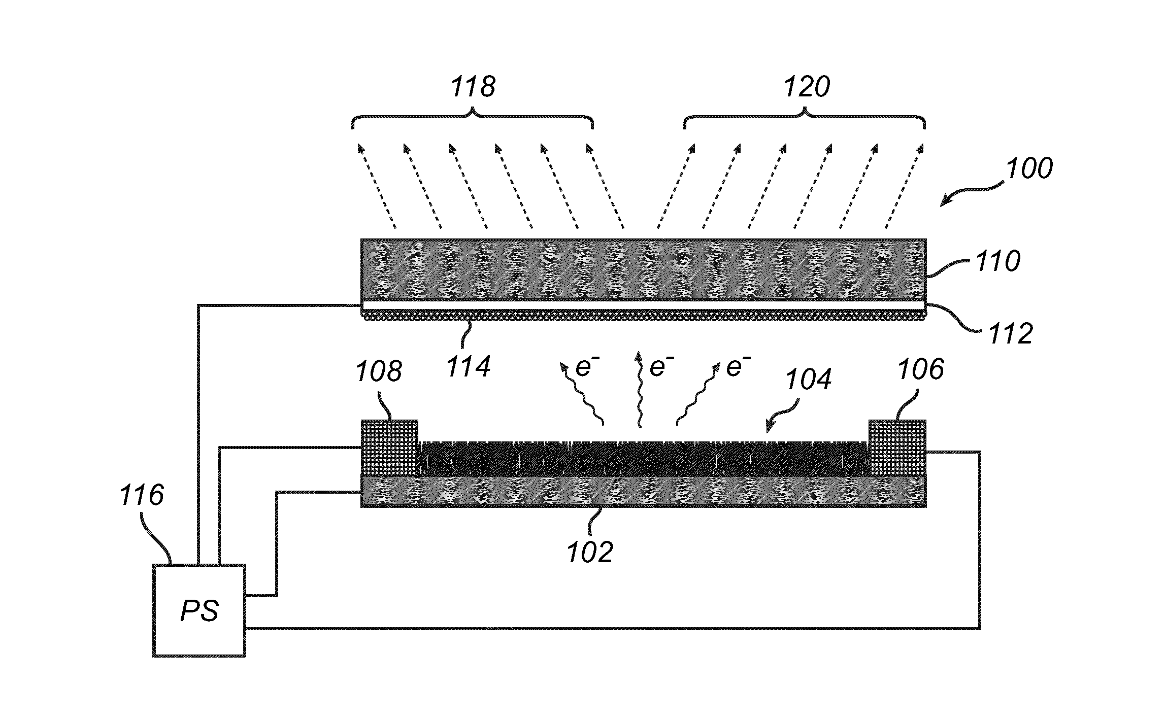
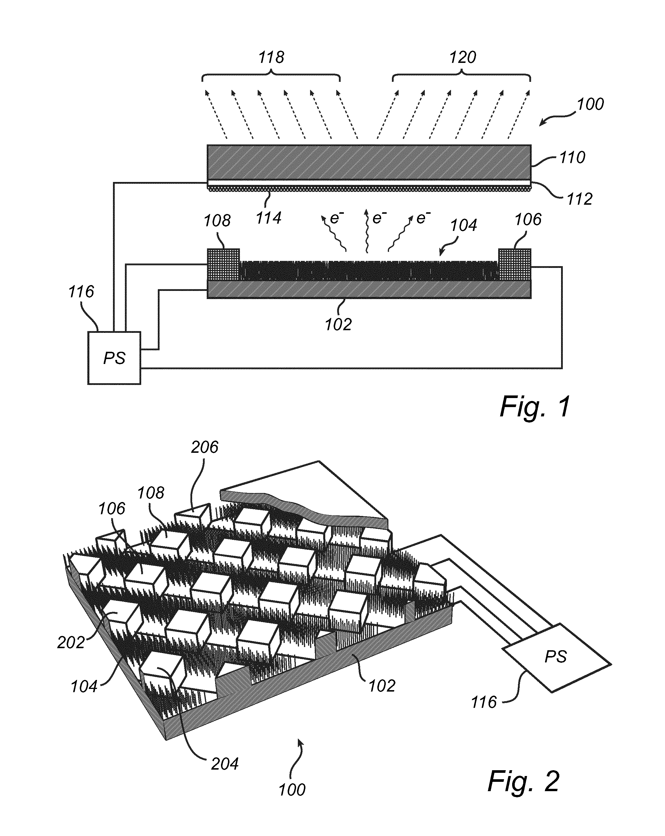
[0025]Referring now to the drawings and to FIG. 1 in particular, there is depicted a side view of a field emission lighting arrangement 100 according to a currently preferred embodiment of the invention. The field emission lighting arrangement 100 comprises a substrate 102 onto which a plurality of sharp emitters has been provided, forming a field emission cathode 104. The sharp emitters may for example comprise ZnO nanostructures, including for example nano wa...


PUM


Abstract

The present invention relates to a field emission lighting arrangement, comprising an anode structure at least partly covered by a phosphor layer, an evacuated envelope inside of which an anode structure is arranged, and a field emission cathode, wherein the field emission lighting arrangement is configured to receive a drive signal for powering the field emission lighting arrangement and to sequentially activate selected portions of the phosphor layer for emitting light. The same control regime may be applied to an arrangement comprising a plurality of field emission cathodes and a single field emission anode. Advantages with the invention includes increase lifetime of the field emission lighting arrangement.

Description

TECHNICAL FIELD[0001]The present invention relates to a field emission lighting arrangement. More specifically, the invention relates to a field emission lighting arrangement where selected portions of a phosphor layer are sequentially activated for emitting light. The invention also relates to a corresponding field emission lighting system.BACKGROUND OF THE INVENTION[0002]There is currently a trend in replacing the traditional light bulb with more energy efficient alternatives. Florescent light sources also in forms resembling the traditional light bulb have been shown and are often referred to as compact fluorescent lamps (CFLs). As is well known, all florescent light sources contain a small amount of mercury, posing problems due to the health effects of mercury exposure. Additionally, due to heavy regulation of the disposal of mercury, the recycling of florescent light sources becomes complex and expensive.[0003]Accordingly, there is a desire to provide an alternative to floresce...

Claims


Application Information

Patent Timeline
IPC IPC(8): H01J63/04H05B41/36
CPCH05B41/36H01J63/04H01J1/304H01J61/523H01J63/02H01J63/06
Inventor HU, QIU-HONG
Owner PUREFIZE TECH AB
Why Eureka
Eureka Blog
Learn More