E-fuse array circuit and programming method of the same

a technology of array circuit and programming method, applied in the field of e-fuse array circuit, can solve the problems of gate oxide being or not being easily destroyed, unable to program fuse, and dimensional restrictions, and achieve the effect of improving the reliability of program operation

Active Publication Date: 2014-03-06
SK HYNIX INC
View PDF0 Cites 4 Cited by
  • Summary
  • Abstract
  • Description
  • Claims
  • Application Information

AI Technical Summary

Benefits of technology

[0025]Exemplary embodiments of the present invention are directed to prevent an increase in program operation time while improving the reliability of a program operation of an e-fuse array circuit.

Problems solved by technology

Therefore, it is possible to set a fuse in the stage of wafer, but after the wafer is mounted on a package, the fuse cannot be programmed.
The above two methods, however, have concerns regarding dimensional restrictions because the transistor T that constitutes the e-fuse has to be enlarged or each e-fuse has to be equipped with an amplifier for amplifying data.
The gate oxide may be or may not be easily destroyed based on the characteristics of the transistor.
In short, a resistive memory device may have a failure based on the characteristics of the transistor.

Method used


Image

  • E-fuse array circuit and programming method of the same
  • E-fuse array circuit and programming method of the same
  • E-fuse array circuit and programming method of the same

Examples


Embodiment Construction

[0033]Exemplary embodiments of the present invention will be described below in more detail with reference to the accompanying drawings. The present invention may, however, be embodied in different forms and should not be construed as limited to the embodiments set forth herein. Rather, these embodiments are provided so that this disclosure will be thorough and complete, and will fully convey the scope of the present invention to those skilled in the art. Throughout the disclosure, like reference numerals refer to like parts throughout the various figures and embodiments of the present invention.

[0034]FIG. 4 is a block view illustrating an e-fuse array circuit in accordance with an embodiment of the present invention.

[0035]Referring to FIG. 4, the e-fuse array circuit includes a cell array 400, a row circuit 410, a column circuit 420, a comparison circuit 430, and a control circuit 440.

[0036]The cell array 400 includes e-fuses that are arrayed in a plurality of rows and a plurality ...


PUM


Abstract

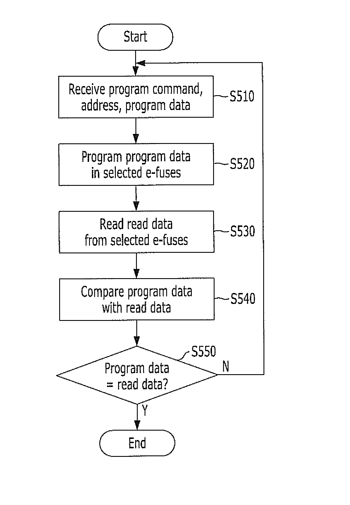
A program method for an e-fuse array circuit includes receiving an address and a multi-bit program data, programming the multi-bit program data in e-fuses designated by the address, reading a multi-bit read data from the e-fuses, and comparing bits of the multi-bit program data with bits of the multi-bit read data, wherein if the bits of the multi-bit program data are identical to the bits of the multi-bit read data, a program operation is terminated; and if the bits of the multi-bit read data are not identical to the bits of the multi-bit program data, then the programming of the multi-bit program data, the reading of the multi-bit read data, and the comparing of the bits are performed again.

Description

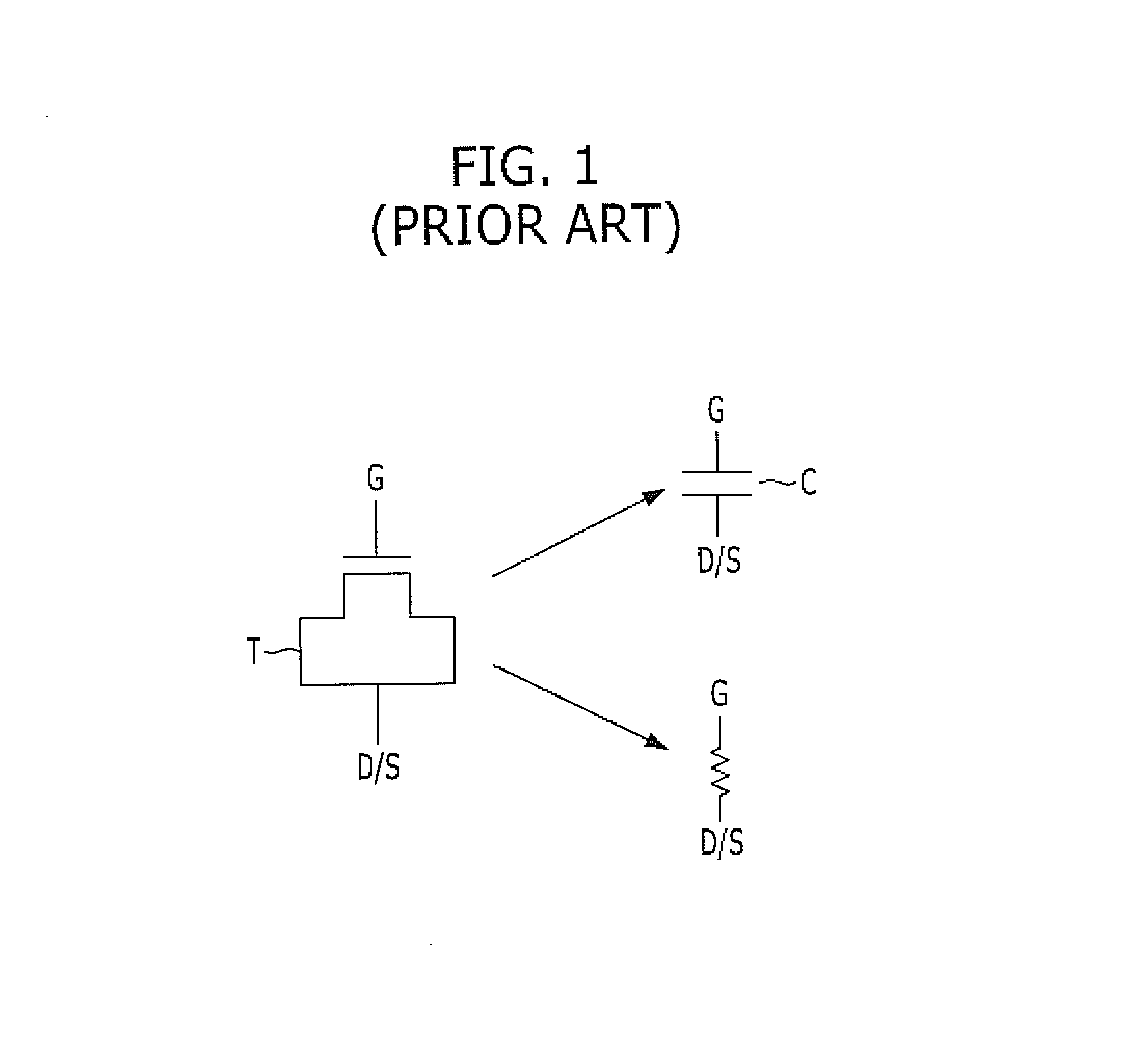
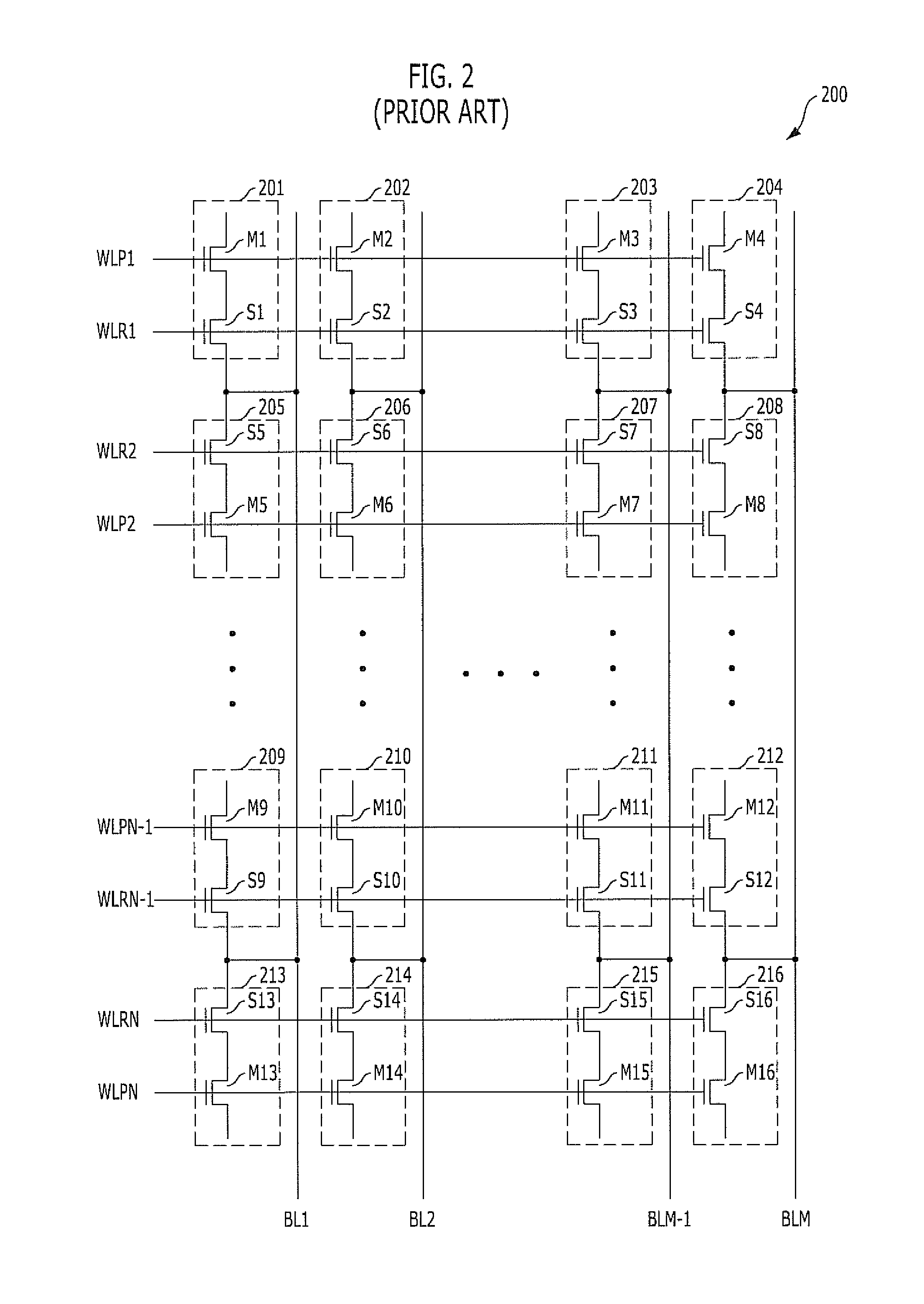
BACKGROUND[0001]1. Field[0002]Exemplary embodiments of the present invention relate to an e-fuse array circuit, and more particularly, to a technology for improving a programming method of an e-fuse array circuit.[0003]2. Description of the Related Art[0004]A general fuse recognizes a data based on whether the fuse is cut by a laser or not. Therefore, it is possible to set a fuse in the stage of wafer, but after the wafer is mounted on a package, the fuse cannot be programmed.[0005]To overcome the drawback, an e-fuse is used. The e-fuse stores a data by using a transistor and changing the resistance between a gate and a drain / source of the transistor.[0006]FIG. 1 illustrates an e-fuse including a transistor, where the e-fuse operates as either a resistor or a capacitor.[0007]Referring to FIG. 1, the e-fuse includes a transistor T, and a power source voltage is supplied to a gate G while a ground voltage is supplied to a drain / source D / S.[0008]If a power source voltage of an ordinary...

Claims


Application Information

Patent Timeline
Patent Type & Authority Applications(United States)
IPC IPC(8): G11C17/16
CPCG11C17/16G11C17/18G11C17/00
Inventor YOON, HYUNSUSEO, YONGHO
Owner SK HYNIX INC
Why Eureka
Try Eureka