
Motion correction system and method for an x-ray tube

a motion correction and x-ray tube technology, applied in the field of x-ray tubes, can solve the problems of unnecessarily increasing the time and cost of imaging the object, and general undesirable performan

Inactive Publication Date: 2014-03-06
GENERAL ELECTRIC CO
View PDF25 Cites 7 Cited by
  • Summary
  • Abstract
  • Description
  • Claims
  • Application Information

AI Technical Summary

Benefits of technology

The present disclosure is related to a motion correction system for an x-ray tube. This system includes a sensor that can measure how far the electron beam generated by the x-ray tube is placed from its intended location due to movement. A control unit analyzes the sensor data and generates a signal to indicate the deviation in the beam's position. A deflection unit then uses this control signal to adjust the beam's direction so that it reaches its intended location. This invention improves the accuracy of x-ray imaging by reducing blur and other motion-related effects.

Problems solved by technology

However, when the x-ray tube is in motion, such as may happen with a portable x-ray device, for example, the focal spot of the electron beam may move away from a determined location during the exposure time.
However, these techniques are related to post processing of the image to correct the motion blur, and not related to correcting the deviation of the electron beam or the motion of the x-ray tube itself.
Also, since the motion deblurring technique is performed after the image is produced, the time and cost for imaging the object is unnecessarily increased and the performance is in general undesirable.

Method used


Image

  • Motion correction system and method for an x-ray tube
  • Motion correction system and method for an x-ray tube
  • Motion correction system and method for an x-ray tube

Examples


Embodiment Construction

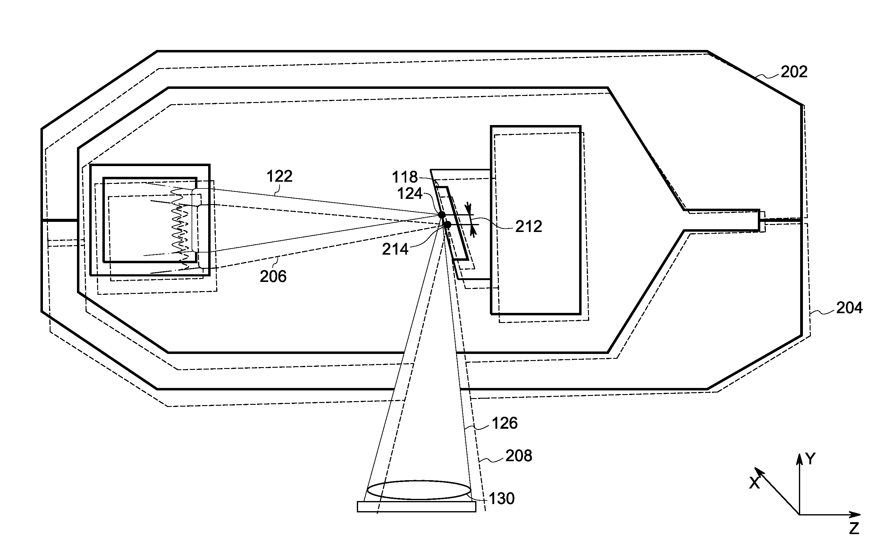
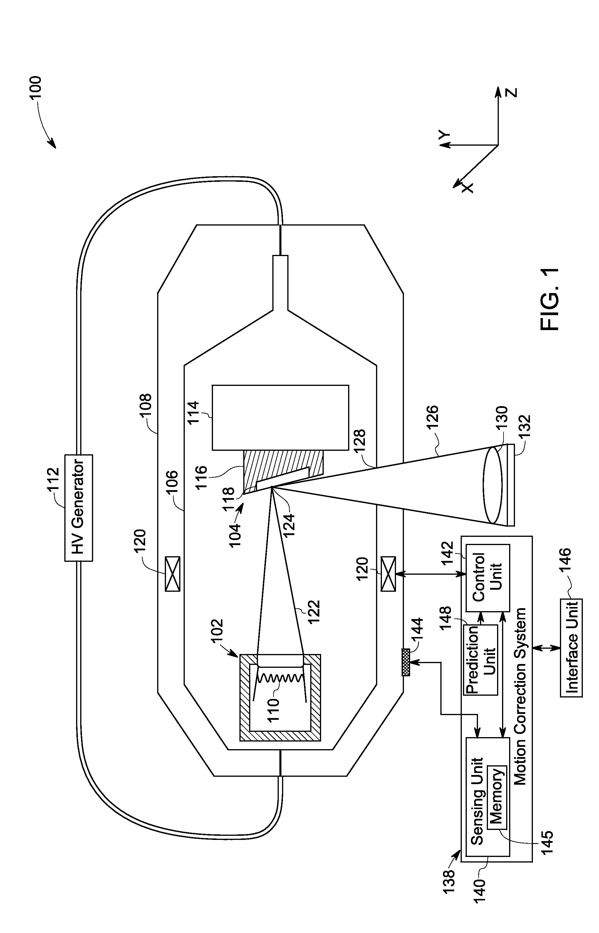
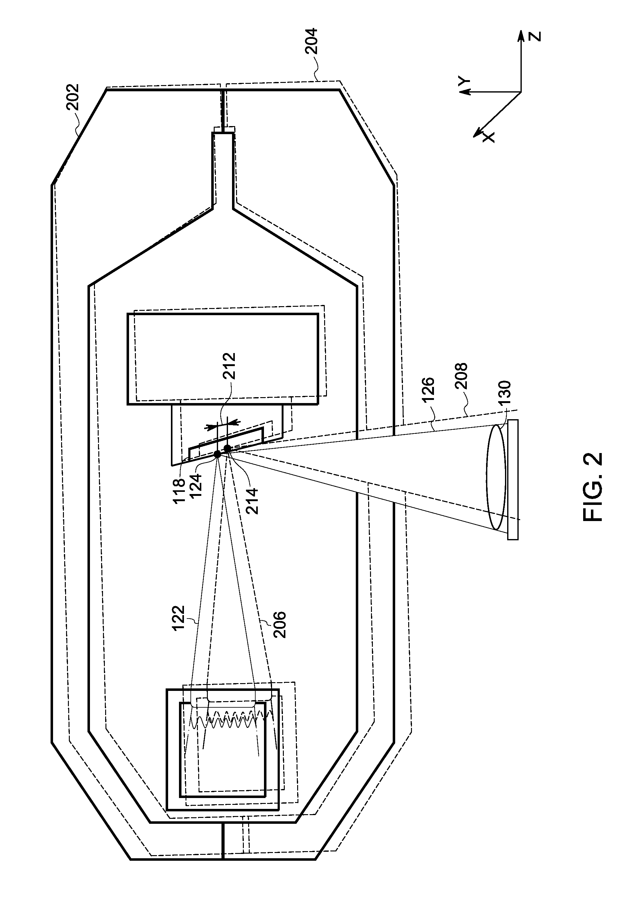
[0018]As will be described in detail hereinafter, various embodiments of exemplary structures and methods for correcting motion of an x-ray tube are presented. By employing the methods and the various embodiments of the motion correction system described hereinafter, motion blur in a produced image is prevented, thereby substantially reducing the need for post-acquisition motion correction processing. Also, the cost and time for producing an image of an object is substantially reduced.

[0019]Turning now to the drawings, and referring to FIG. 1, a block diagram of an x-ray tube 100, in accordance with aspects of the present disclosure, is depicted. The x-ray tube 100 is configured for emitting x-rays towards a material sample, a patient, or an object under scan. The x-ray tube 100 includes a cathode unit 102 and an anode unit 104 that are disposed within an evacuated enclosure 106. The evacuated enclosure 106 may be a vacuum chamber that is positioned within a housing 108 of the x-ray...


PUM


Abstract

A motion correction system and method for motion correction for an x-ray tube is presented. One embodiment of the motion correction system includes a sensing unit coupled to an x-ray tube to determine a distance with which an impingement location of an electron beam generated by the x-ray tube deviates from a determined location due to motion of the x-ray tube. The motion correction system further includes a control unit coupled to the sensing unit to generate a control signal corresponding to the distance with which the impingement location of the electron beam deviates. Also, the motion correction system includes a deflection unit coupled to the control unit to steer the electron beam to the determined location based on the generated control signal.

Description

BACKGROUND[0001]Embodiments of the present disclosure relate generally to an x-ray tube, and more particularly to a method and a system for correcting focal spot location deviation due to the motion of the x-ray tube.[0002]Traditional x-ray imaging systems include an x-ray source and a detector array. The x-ray source generates x-rays that pass through an object under scan. These x-rays are attenuated while passing through the object and are received by the detector array. The detector array includes detector elements that produce electrical signals indicative of the attenuated x-rays received by each detector element. Further, the produced electrical signals are transmitted to a data processing system for analysis, which ultimately produces an image.[0003]Typically, the x-ray source includes an x-ray tube that generates x-rays when an electron beam impinges on a focal spot of an anode surface. However, when the x-ray tube is in motion, such as may happen with a portable x-ray devic...

Claims


Application Information

Patent Timeline
Patent Type & Authority Applications(United States)
IPC IPC(8): H01J35/30
CPCH01J35/025H01J35/153H01J35/28
Inventor ZOU, YUNZELAKIEWICZ, SCOTT STEPHENJANSEN, FLORIBERTUS P. M. HEUKENSFELDTEBERHARD, JEFFREY WAYNETAO, FENGFENGPOWERS, TIMOTHYSJOBERG, THOMAS EDMUND
Owner GENERAL ELECTRIC CO
Learn More