Method of Fabricating a Curved Composite Structure Using Composite Prepreg Tape

a composite structure and prepreg tape technology, applied in lamination ancillary operations, thin material processing, chemistry apparatus and processes, etc., can solve the problems of increasing material costs, time-consuming techniques, and cured parts having the desired mechanical strength

Active Publication Date: 2014-03-06
THE BOEING CO
View PDF2 Cites 31 Cited by
  • Summary
  • Abstract
  • Description
  • Claims
  • Application Information

AI Technical Summary

Benefits of technology

[0006]Accordingly, there is a need for a method of laying up and forming curved composite plies, especially 0 degree plies, using substantially straight unidirectional prepreg tape. T

Problems solved by technology

These techniques can be time consuming and/or may not result in a cured part having the desired mechanical strength.
However the use of slit tape may increase material costs and reduce production rates since laying

Method used


Image

  • Method of Fabricating a Curved Composite Structure Using Composite Prepreg Tape
  • Method of Fabricating a Curved Composite Structure Using Composite Prepreg Tape
  • Method of Fabricating a Curved Composite Structure Using Composite Prepreg Tape

Examples


Embodiment Construction

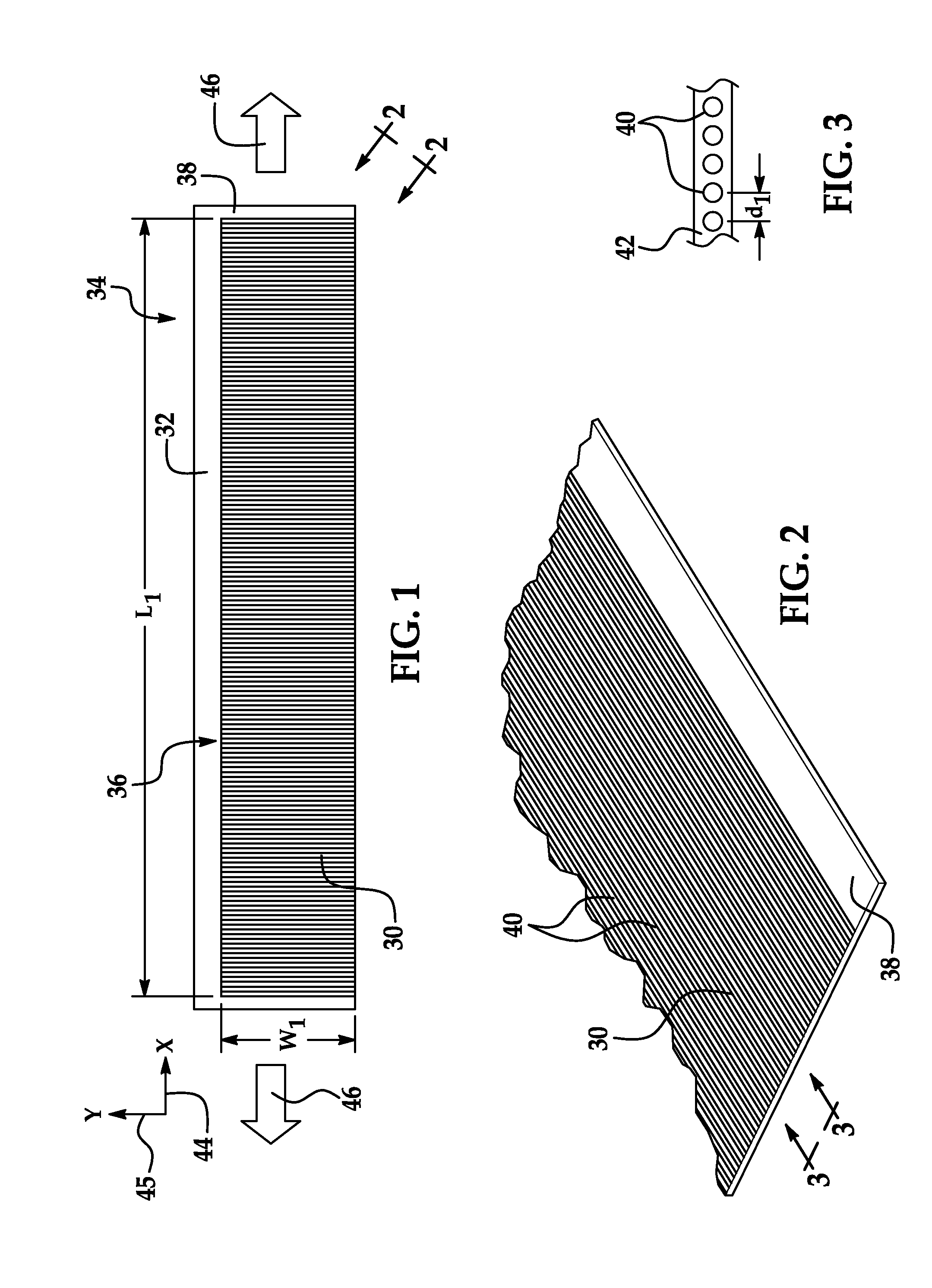
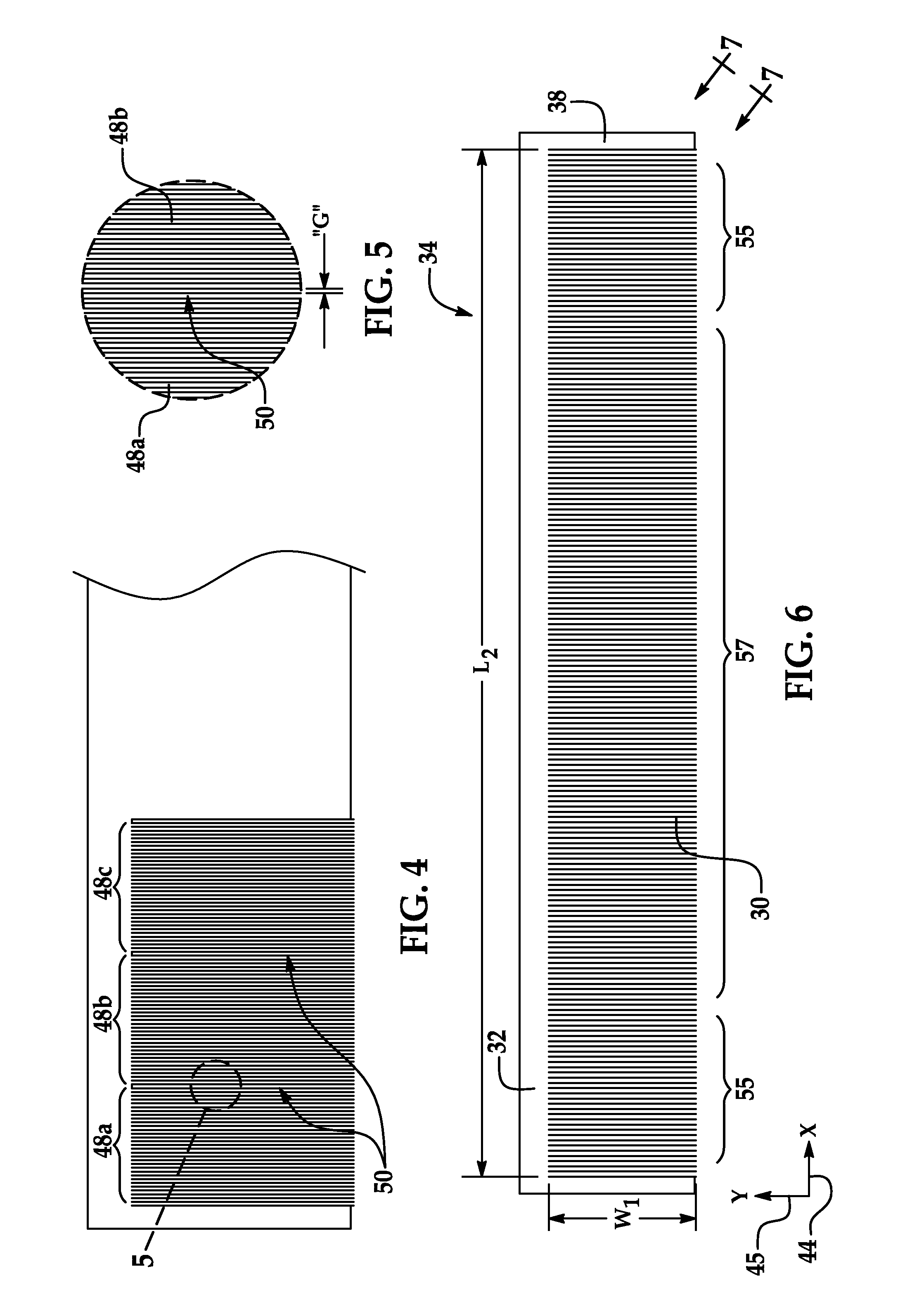
[0045]Referring first to FIGS. 1, 2 and 3, a ply 30 of composite resin material is held in face-to-face contact on a carrier film 32 to form a ply carrier assembly 34. The carrier film 32 may be used to transport the ply 30 and / or to apply the ply 30 to a tool (not shown) during a layup process for producing a composite part layup (not shown). In the example illustrated in FIGS. 1-3, the ply 30 may be a prepreg that includes unidirectional reinforcing fibers 40 having a 90 degree orientation, however other plies (not shown) in the part layup may have other fiber orientations based on a predefined ply schedule.

[0046]The fibers 40 are pre-impregnated with a suitable polymer resin 42 which acts as a matrix to hold the fibers 40 in the desired orientation following curing. The composite ply 30 has a length L1 and a width W1 prior to being deformed during the layup process, as will be described in more detail below. The ply 30 is adhered to the carrier film 32 by the tackiness of the unc...


PUM

PropertyMeasurementUnit
Angleaaaaaaaaaa
Lengthaaaaaaaaaa
Structureaaaaaaaaaa

Abstract

A method is provided of fabricating a composite stiffener having a curved web and at least one curved flange. A substantially straight length of unidirectional prepreg tape is placed on a carrier. The at least one curved flange is formed by using the carrier to steer a first portion of the tape onto a first curved tool surface. The curved web is formed by using the carrier to form a second portion of the tape onto a second curved tool surface.

Description

CROSS REFERENCE TO RELATED APPLICATIONS[0001]This application is a continuation-in-part of U.S. patent application Ser. No. 12 / 945,024 filed Nov. 12, 2010, and published May 17, 2012 as US Patent Publication No. 20120121866, the entire disclosure of which is incorporated by reference herein.BACKGROUND INFORMATION[0002]1. Field:[0003]This disclosure generally relates to processes for fabricating curved composite structures, and deals more particularly with a method of fabricating composite structures such as stiffeners having compound curves using composite prepreg tape.[0004]2. Background:[0005]During layup of prepreg plies over a tool, it is sometimes necessary to closely conform the plies to curves, contours and / or features of the tool in order to assure that the fibers follow the load path, and the layup is dimensionally accurate and substantially free of voids, wrinkling and / or buckling. Known techniques for conforming plies to curved tool surfaces involve darting, cutting and / o...

Claims


Application Information

Patent Timeline
IPC IPC(8): B32B38/00
CPCB32B38/0012B29C70/541Y10T156/1002Y10T428/2419Y10T428/24628B29C70/302
Inventor SMITH, JR., DANIEL RICHARDMODIN, ANDREW E.DEPASE, EDOARDODARROW, DONALD CHESTERKLEWIADA, MARK
Owner THE BOEING CO
Why Eureka
Try Eureka