Apparatus for Performing a Centrifugal Field-Flow Fractionation Comprising a Seal and Method

a technology of centrifugal field and seal, applied in the direction of centrifuges, separation processes, instruments, etc., can solve problems such as leakage, and achieve the effect of avoiding leakage potential and reducing leakag

Active Publication Date: 2014-03-06
POSTNOVA ANALYTICS
View PDF0 Cites 7 Cited by
  • Summary
  • Abstract
  • Description
  • Claims
  • Application Information

AI Technical Summary

Benefits of technology

[0033]As an advantage, this leads to a reduced leakage as the sample fluid line can be introduced further into the shaft wh

Problems solved by technology

Hence, there is a large area av

Method used


Image

  • Apparatus for Performing a Centrifugal Field-Flow Fractionation Comprising a Seal and Method
  • Apparatus for Performing a Centrifugal Field-Flow Fractionation Comprising a Seal and Method
  • Apparatus for Performing a Centrifugal Field-Flow Fractionation Comprising a Seal and Method

Examples


Embodiment Construction

[0042]A preferred way of carrying out the invention will now be described with reference to the accompanying drawings.

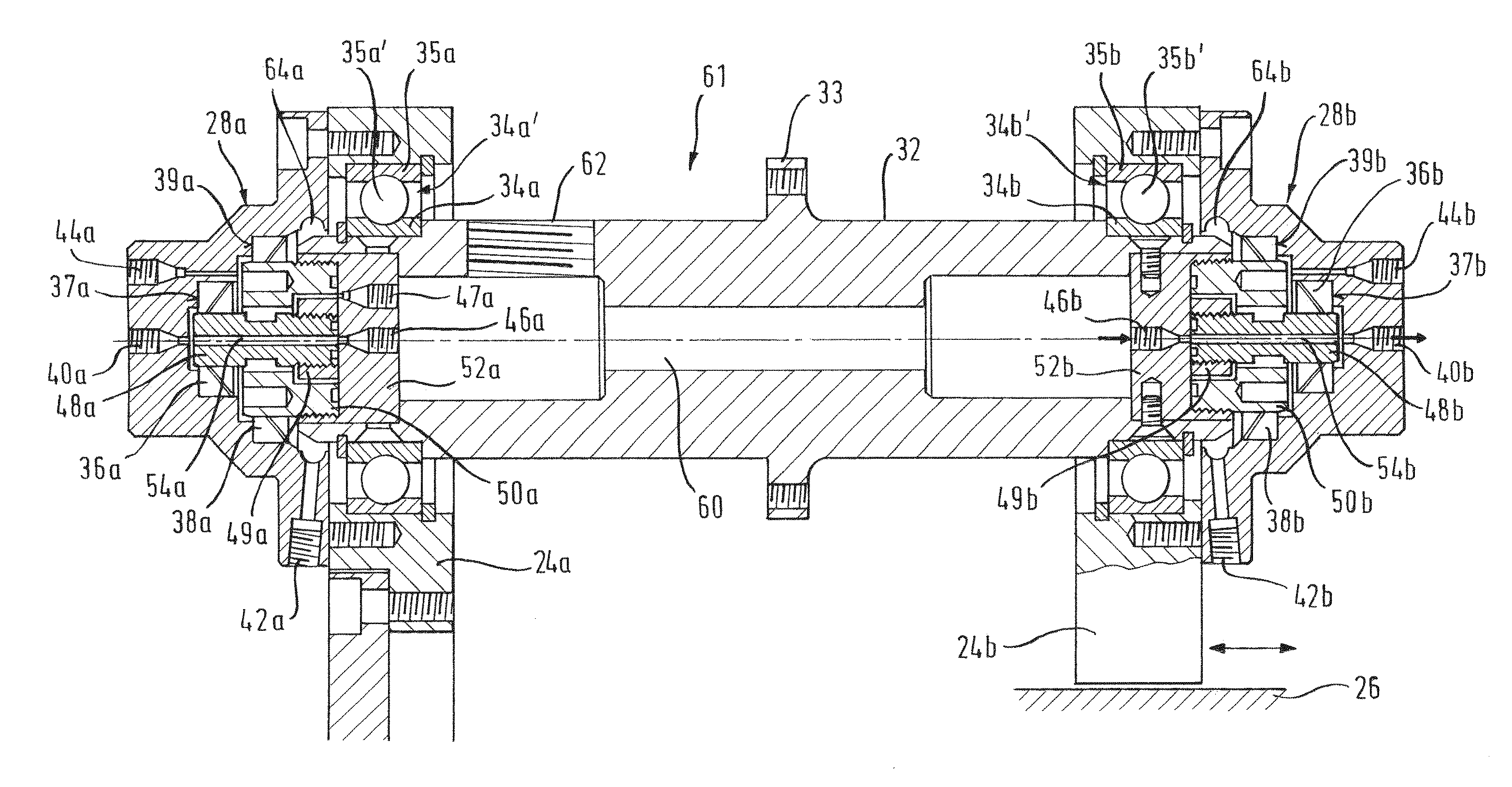
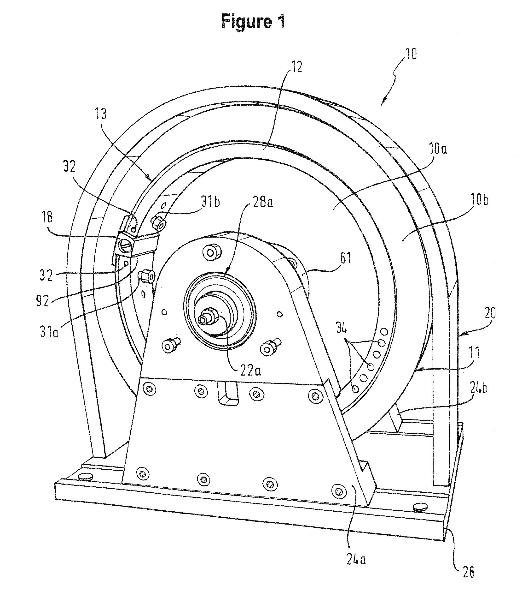
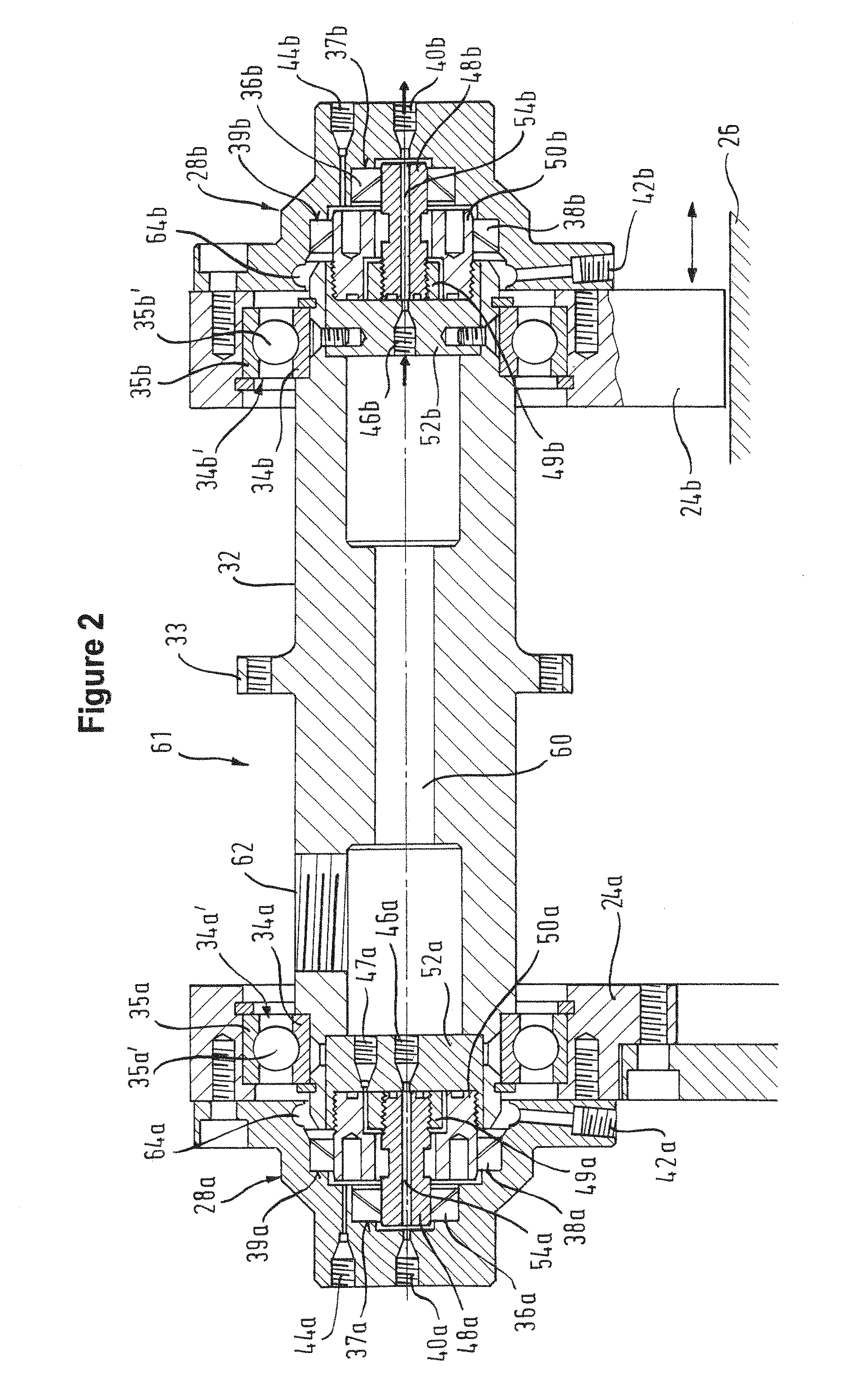
[0043]FIG. 1 shows an assembled centrifugal field-flow fractionation apparatus 10 according to the invention. It should be noted that end caps 28a / b, which will be described in more detail further below, are missing in this Figure but will be attached before operation of the FFF apparatus. The drawing shows a rotor 10a which can be rotated about a shaft 61 (shown in more detail in FIG. 2). The shaft, in turn, comprises several individual pieces. The rotor 10a is driven by a DC electric motor (not shown). The rotor 10a has a generally bowl-shaped structure, with a hub 10b as a radially inner part and a rim 11 as a radially outer part. The hub is essentially disc-shaped, with a circular outer circumference. The outer rim 11 is annular, with a rectangular cross-section, and extends circumferentially around the hub 10b as well as axially beyond the hub 10b. Thus, the ove...


PUM

PropertyMeasurementUnit
Pressureaaaaaaaaaa
Pressureaaaaaaaaaa
Forceaaaaaaaaaa

Abstract

The current invention relates to an apparatus for performing a centrifugal field-flow fractionation. In particular, in the apparatus according to the invention, radial rotary shaft seals are used for sealing the rotating parts of the shaft for carrying out the centrifugal field-flow fractionation and the stationary parts. Furthermore, a separate line is introduced for reducing the pressure differential across these seals. In such way, the driving force driving sample fluid across the seals is reduced, thereby reducing leakage.

Description

TECHNICAL AREA[0001]The invention relates to an apparatus for performing a centrifugal field-flow fractionation according to the preamble of claim 1 as well as to a method for performing a centrifugal field-flow fractionation.[0002]Field-Flow Fractionation (FFF) is a family of unique separation techniques, comprising various different sub-techniques. All FFF techniques utilize the same basic separation principle, but employ different separation fields. Depending on the separation field, the technique is called Flow FFF, Sedimentation FFF, Thermal FFF, etc. FFF is providing fast, gentle and high resolution separations of particulate matter from 1 nm up to 100 μm in liquid media. The sample is separated inside a longitudinal, open flow channel without the presence of any packing or stationary phase inside the channel. The FFF apparatus are typically arranged so that the fluid inside the channel forms a laminar flow with a parabolic stream profile.[0003]The different force fields used,...

Claims


Application Information

Patent Timeline
IPC IPC(8): B04B9/12B04B15/06
CPCB04B15/06B04B9/12B04B5/0442B04B11/02G01N30/0005G01N2030/002B04B2005/045
Inventor WELZ, ROLAND
Owner POSTNOVA ANALYTICS
Why Eureka
Try Eureka