Cable tie

Active Publication Date: 2014-03-13
TAIWAN PAIHO LTD
View PDF1 Cites 10 Cited by
  • Summary
  • Abstract
  • Description
  • Claims
  • Application Information

AI Technical Summary

Benefits of technology

[0011]In order to solve the problems exist in the currently-available cable ties, the present invention provides a cable tie including a stripe body having a first surface and a second surface opposite to the first surface. A plurality of convex portions are disposed on the first surface in a regularly arranged manner. A first end of the stripe body has a stationary portion, while a second end opposite to the first end has a movable portion. A pawl hole and a pawl are formed on the movable portion, and the width of the pawl hole is greater than that of the movable portion. Each of the convex portions of the stripe body has a hook-like structure, and tips of the hook-like structures are oriented toward a fixed direction. Therefore, at least one of the hook-like structure engage the pawl when the movable portion of the stripe body passes through the pawl hole for achieving a securing effect.
[0012]The main objective of the present invention is to provide a cable tie comprising a stripe body, wherein convex portions of the stripe body have hook-like structures, and tips of the hook-like structures are oriented toward a fixed direction. Therefore, the hook-like structures can engage the pawl after the stripe body has passed through the pawl hole, and enable the cable tie to tightly bind an object to be bound with a single structure.
[0013]Another objective of the present invention is to provide a cable tie comprising a stripe body, wherein convex portions of the stripe body have hook-lik

Problems solved by technology

On the other hand, an unreleasable cable tie is the one that does not allow the teeth of the tape body engaged with the teeth-like structure in the slot to be released.
In the unreleasable cable tie case, once the tape body of the cable tie is inserted into the slot for engagement, the only thing to do with the cable tie is to pull the tape body to make the resulted close loop become tighter, and the cable tie is not able to be disabled without cutting or damaging.
Thus, an unreleasable cable tie is for single use only.
Currently, it is unavoidable that a cable tie would have an excess portion after the resulted close loop being pulled tight for secu

Method used


Image

  • Cable tie
  • Cable tie
  • Cable tie

Examples


Embodiment Construction

[0021]In order to enable those skilled in the art to further understand the object, technical features and advantages of the present invention, and to implement the present invention, the technical features and implementing method are illustrated in the following description and further demonstrated with preferred embodiments. However, the following description for the embodiments is not for limiting the present invention. Also, the drawings referred in the following text are schematically related to the features of the present invention.

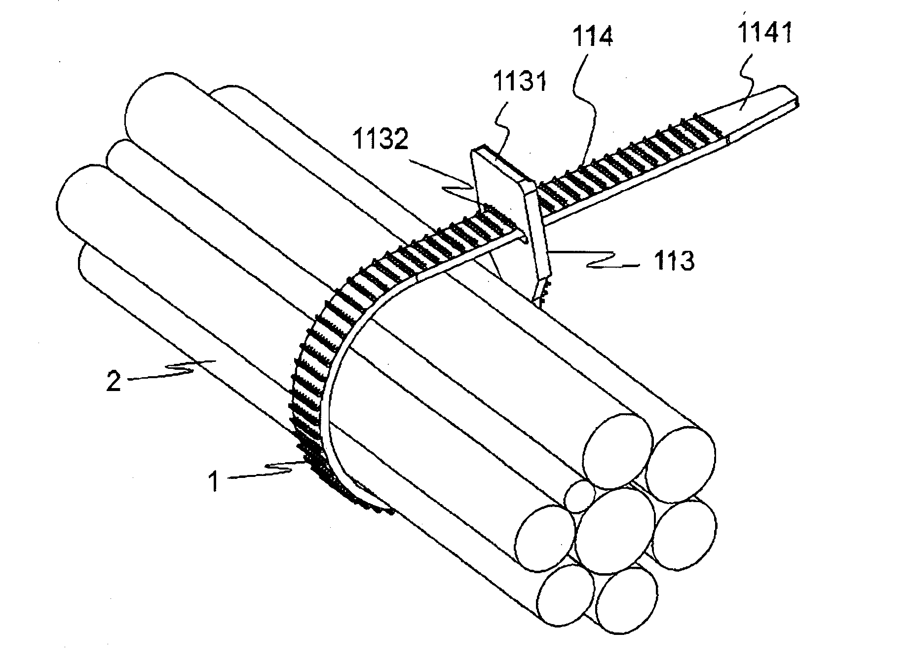
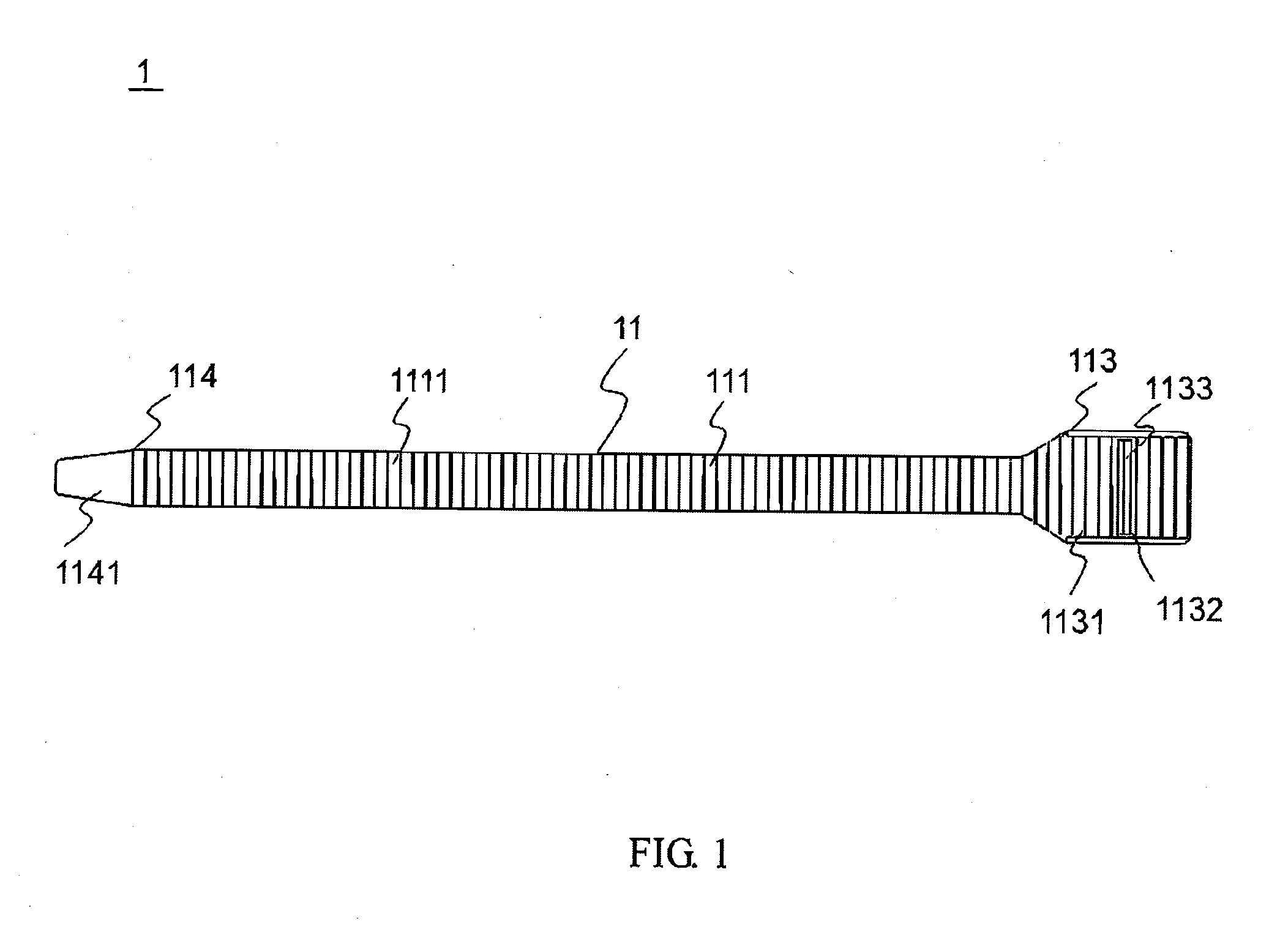
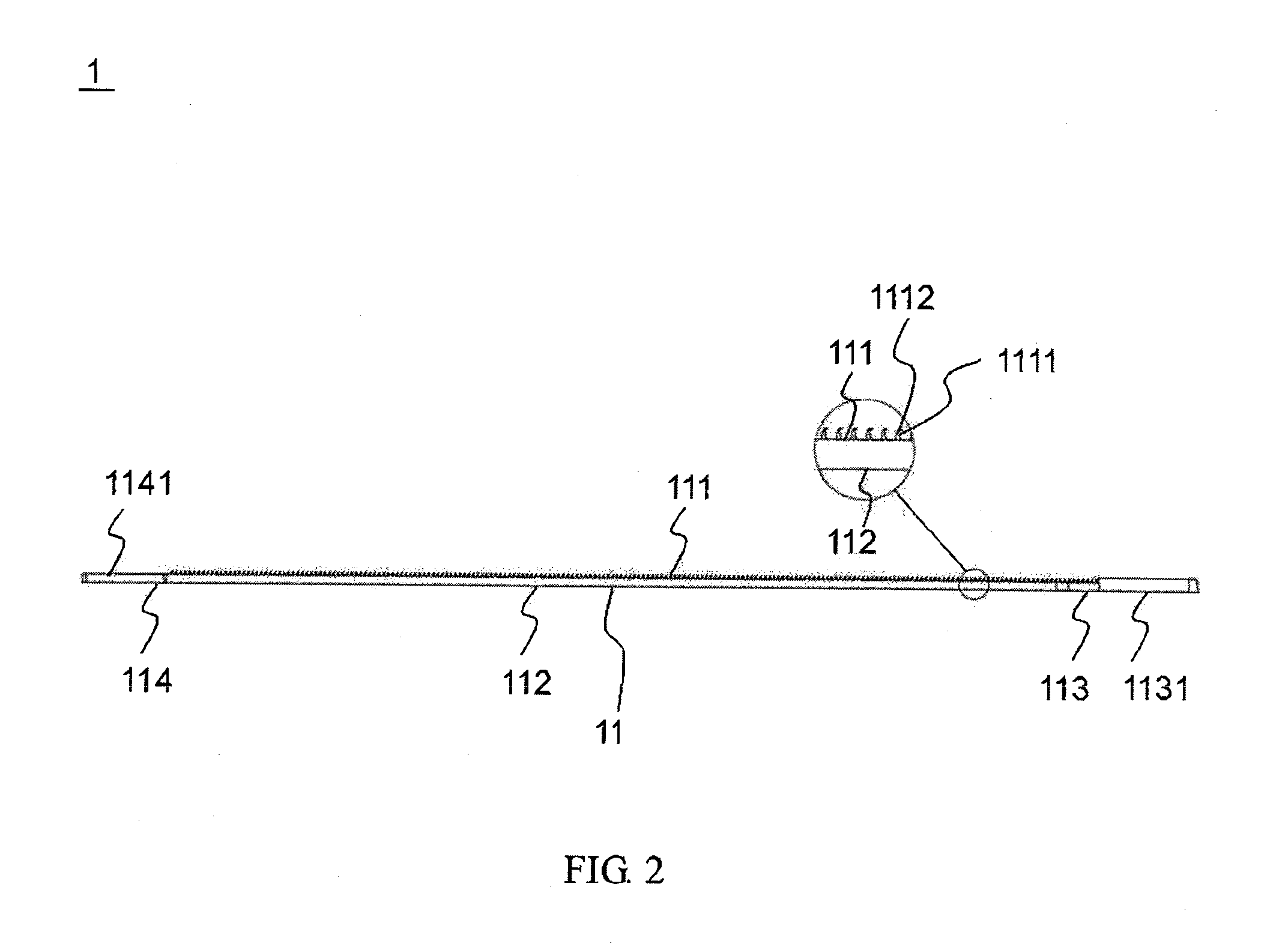
[0022]First, please refer to FIG. 1 and FIG. 2, which are top view and side view of a cable tie proposed in an embodiment of the present invention, respectively. As shown in FIG. 1, the cable tie 1 comprises a stripe body 11 having a first surface 111, such as the upper surface, and a second surface 112, such as the lower surface. Regularly arranged multiple convex portions 1111 are provided on the first surface 111. The width and height of these co...


PUM


Abstract

The present invention provides a cable tie including a stripe body having a first surface and a second surface opposite to the first surface. A plurality of convex portions are disposed on the first surface in a regularly arranged manner. A first end of the stripe body has a stationary portion, while a second end opposite to the first end has a movable portion. A pawl hole and a pawl are formed on the movable portion, and the width of the pawl hole is greater than that of the movable portion. Each of the convex portions of the stripe body has a hook-like structure oriented toward the first end. Therefore, the hook-like structures engage the pawl when the movable portion of the stripe body passes through the pawl hole for achieving a securing effect.

Description

BACKGROUND OF THE INVENTION[0001]1. Technical Field[0002]The present invention relates to a cable tie and, in particular, to a cable tie formed with hook-like structures.[0003]2. Description of the Prior Art[0004]Cable ties are used widely in daily life, and are frequently used for securing or binding objects. Due to the capability of easily being used, carried, stored, and high safety in operation, cable ties are strongly demanded by people.[0005]Well-known cable ties can be classified into unreleasable cable ties and releasable cable ties. Both types of cable ties are operated on the same concept basis. That is a slot is formed at an end of the cable tie with a teeth-like structure to be engaged with teeth formed on a tape body of the same cable tie so as to tightly secure the object to be bound for the convenience of tidying.[0006]A common releasable cable tie is referred to one having the capability of allowing the teeth on the tape body engaged with the teeth-like structure in ...

Claims


Application Information

Patent Timeline
IPC IPC(8): B65D63/10
CPCB65D63/1063F16L3/233B65D63/1027Y10T24/1498
Inventor CHENG, ALLEN
Owner TAIWAN PAIHO LTD
Why Eureka
Try Eureka