Tobacco free hookah smoking system

Inactive Publication Date: 2014-03-13
BEDROCK HLDG TRUST 2012
0 Cites 41 Cited by

AI-Extracted Technical Summary

Problems solved by technology

This patent describes a smoking apparatus which efficiently removes harmful impurities from the smoke and does so by improving contact between the smoke and a washing liquid but does not offer clay porous spheres (or like material) as the alternative to tobacco in a hookah smoking system or the Ready Pack Smoke Cups containing the Hydroton® clay or Growstones® glass (or a like substance) porous spheres or the embodiment that will have the Cup Holder to be filled with recycled porous spheres or porous spheres that have been purchased in bulk.
Wood is known to generate toxic materials when bu...

Benefits of technology

[0008]U.S. Pat. No. 4,682,610 of Kenneth W. Freelain describes a smoking apparatus which efficiently removes harmful impurities from the smoke and does so by improving contact between the smoke and a washing liquid. This is ...

Abstract

The present invention is directed to a Tobacco Free Hookah Smoking System that will have a head (bowl) at the upper end of a tubular stem that extends into the jar or Shisha containing water. One or more additional tubular members extend out of the Shisha making up the inhaling tube and the check valve. The spheres will be made from porous materials such as Hydroton® synthetic clay, or Growstones® glass (or a like substance) other stone materials, cobblestone, and other natural and synthetic porous materials. The spheres will be made by soaking in a solution of sweetener, glycerin and various flavorings along with the added option of herbal extracts/oils, vitamins, and other medical/health compounds. Ready Pack Smoke Cups containing the spheres will be available. An alternate embodiment will have the Cup Holder that can be filled with recycled porous spheres or porous spheres that have been purchased in bulk.

Application Domain

Technology Topic

GrowstonesHookah Smoking +6

Image

  • Tobacco free hookah smoking system
  • Tobacco free hookah smoking system
  • Tobacco free hookah smoking system

Examples

  • Experimental program(1)

Example

[0052]For a fuller understanding of the nature and advantages of the Tobacco Free Hookah Smoking System, reference should be had to the following detailed description taken in conjunction with the accompanying drawings which are incorporated in and form a part of this specification, illustrate embodiments of the design and together with the description, serve to explain the principles of this application.
DETAILED DESCRIPTION OF THE PREFERRED EMBODIMENTS
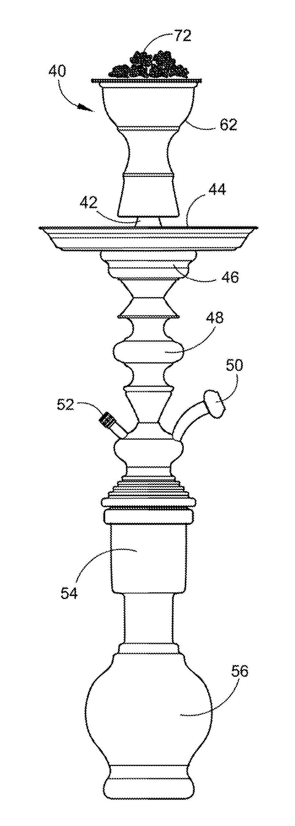
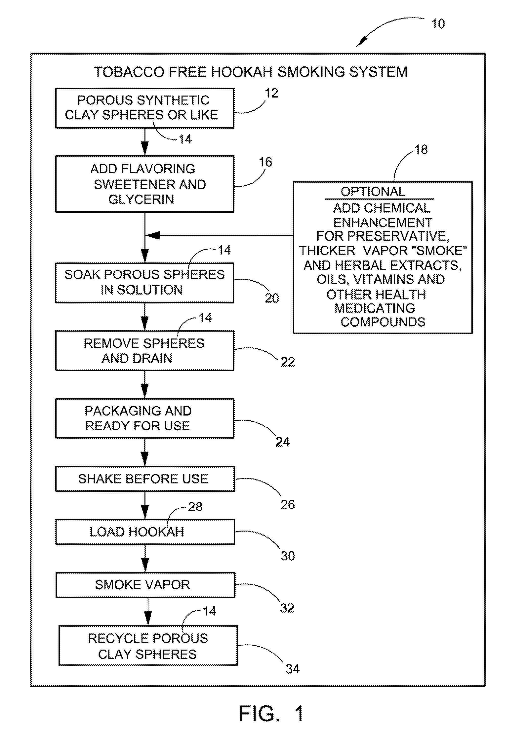
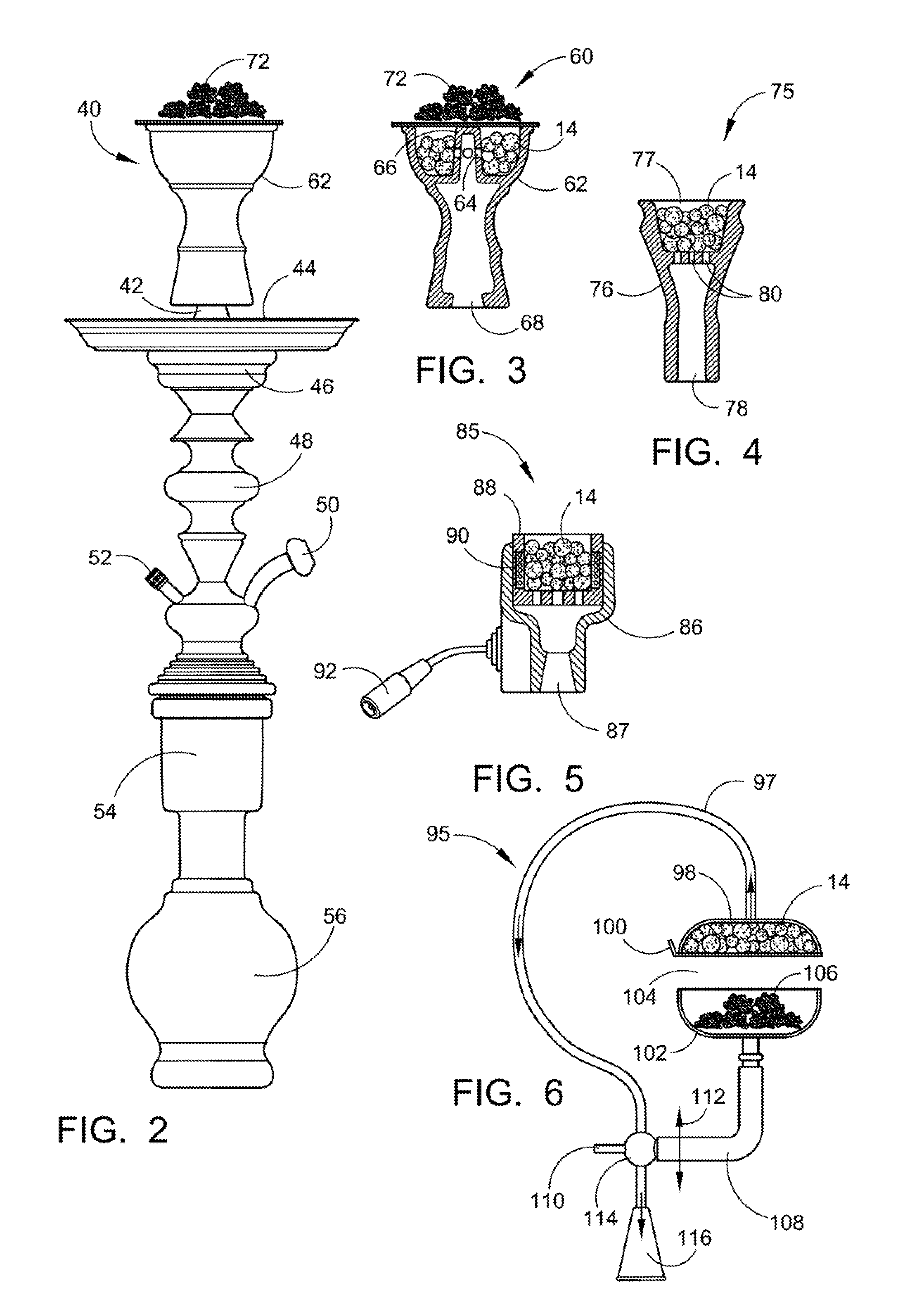
[0053]Referring now to the drawings, wherein similar parts of the Tobacco Free Hookah Smoking System 10 are identified by like reference numerals, there is seen in FIG. 1 a block diagram depicting the operations of the Tobacco Free Hookah Smoking System where block 12 depicts the acquisition of the porous clay spheres 14 from Hydroton® clay or Growstones® glass (or a like substance) and block 16 depicts the adding of flavoring, sweeteners, and glycerin. At this point is the option of adding chemical enhancements for a preservative, thicker smoke vapor and replacing or incorporating with the flavoring herbal extracts/oils, vitamins, and other medicating/health compounds shown in 18. After the porous spheres are soaked in the solution as depicted in block 20 and then the spheres are removed and drained as depicted in block 22 and they are packaged, ready for use shown in block 14. Before the product is used it must be shaken as shown in block 26 to loosen and separate the porous spheres 14. After this, the hookah 28 can be loaded shown in block 30 and smoked as shown in block 32. The porous clay spheres can be recycled for reuse as shown in block 34, or the system may employ new porous spheres 14 that have been purchased individually or in hulk.
[0054]Referring now to FIG. 2 there is shown a typical hookah system 40 illustrated with the preferred head 62 attached thereon. The hookah system 40 comprises a stem 42 for attaching the head to the hookah, and a tray 44 for catching loose and flailing charcoal 72 located on a screen on the top of the head 62. A base section 46 holds the tray 44 in place. A stem section 48 is located below the base section 46. Below that is a middle section including the smoking hose tubular outlet 50 and a smoke check valve 52. The jar or Shisha has an upper section 54 (referred to as the smoke chamber within the jar) and a lower section 56, which holds water for the smoke vapors to pass through.
[0055]Referring now to FIG. 3 there is depicted a cross-sectional view of the preferred head 60 illustrating the relationship between the head 60 containing the spheres 14, the screen, the heat source, in this case, charcoal or coals 72 (which maybe substituted by any heat source, such as electrical) and the position of the holes 64 therein. As can be seen in this illustration, the holes 64 are located in the side wall of a post 66 within the body 62 of head 60. This enables the smoke to pass through unobstructed. It also prevents any liquid which may build up during the smoking process to be caught within the head 60, and thereby not passed into the water contained by the jar or Shisha. The preferred head 60 is attached to the stem of the hookah at orifice 68.
[0056]FIG. 4 depicts a cross-sectional view of a standard head 75 illustrating the relationship between the head body 76 containing the spheres 14, the screen 77, and the position of the boles 80 therein. The standard head 75 is attached to the stem of the hookah at orifice 78.
[0057]FIG. 5 depicts a cross-sectional view of an electrically heated head 85 illustrating the relationship between the head body 86 containing the spheres 14, the screen, the heat source, in this case, electric coils 90 in a ceramic cup 88, and the position of the holes therein. The electrically heated head 85 is attached to the stem of the hookah at orifice 87. The electrically heated head 85 is powered through an adapter that connects to the power cord connector 92.
[0058]FIG. 6 depicts a cross-sectional view of an alternative head 95 illustrating the relationship between the head body upper portion 98 and lower portion 102. The upper portion 98 contains the spheres 14, and the screen 100 holding the spheres in place. The heat source, in this case, charcoal or coals 106 is contained within lower section 102. A lever 119 on joint 114 enables the lower section 102, resting on elbow 108, to be moved and adjusted toward (upward) and away from (downward), see arrows 112, the upper section 98 as needed. The pathway of the smoke vapor therein travels along tube 97 and down through orifice 116 to enter the jar or Shisha (see arrows within the tubular structure shown) the alternative head 95 is mounted to the stem of the hookah at orifice 116.
[0059]FIG. 7 depicts a perspective illustration of the Ready Pack Smoke Cup 140 with the flanged upper surface 142 having the multiple upper surface orifices 144 and the cup side surface 146 broken away showing the spheres (i.e. Hydroton® clay or Growstones® glass (or a like substance) porous spheres) 14, or spheres made from other suitable porous materials, such as porous natural stone, cobblestone, synthetic porous stone-like substances, etc. or the equivalent to same.
[0060]FIG. 8 depicts a cross section of the hookah 126 used in the Tobacco Free Hookah Smoking System 110 where an electrical heating unit 150 is resting on the flanged upper surface 142 above the porous spheres 14. The flanged upper surface 142, which may be made of metal, aluminum, foil sheet, or like material, has the flanged edges 152 bent down around the head (or bowl) 154 that is held on the tubular stem 156 by the means of a flexible seal 158. The electrical heating unit 150 can be replaced by live charcoal or coals as desired. The Tubular stem 156 extends through and into the interior area 162 of the jar or Shisha 164 below the surface of the water 166 where the vapors 168 bubble to the water 166 surface and are drawn out through as short tubular member 170 extending through the jar or Shisha 164 to the inhaling tube 172.
[0061]FIG. 9 depicts a perspective illustration of the top of the Ready Pack Smoke Cup 140 with the cup side surface 146 broken away and the top seal 178 pulled away showing the upper surface orifices 144 and the spheres 14, (i.e. Hydroton® clay or Growstones® glass (or a like substance) porous spheres), or spheres made from other suitable porous materials such as porous natural stone, cobblestone, synthetic porous stone-like substances, etc. or the equivalent to same.
[0062]FIG. 10 depicts a perspective illustration of the bottom surface 180 of the Ready Pack Smoke Cup 140 with the bottom seal 182 pulled away showing the lower surface orifices 184.
[0063]FIG. 11 depicts a perspective illustration of the Cup Holder 188 with the side 190 broken away showing the orifices 192 on the lower surface 194 and the Cover Plate 196 with cover plate orifices 198 raised above.
[0064]FIG. 12 depicts a perspective illustration of the Smoke Cup 204 with the top seal 206 pulled away showing the upper surface 208 with the upper surface orifices 210 and cup side 212 broken away showing the spheres 14 (i.e. Hydroton® clay or Growstones® glass (or a like substance) porous spheres), or spheres made from other suitable porous materials such as porous natural stone, cobblestone, synthetic porous stone-like substances, etc. or the equivalent to same.
[0065]FIG. 13 depicts a perspective illustration of the cup side 212 and cup lower (bottom) surface 220 of the Smoke Cup 204 with the bottom seal 216 pulled away showing the lower surface orifices 218 on the cup lower surface 220.
[0066]FIG. 14 depicts cross-sectional view of a portable electronic hookah 230 which may be alternatively used to electronically smoke or vaporize the spheres 234, illustrating the relationship between the compartment or cartridge housing 232 containing the spheres 234, the atomizer or vaporizer 236 heat source and the battery 238 which powers the atomizer or vaporizer 236. The portable electronic hookah (also known as an e-hookah) 230 is normally used with liquid loaded in the cartridge housing 232 for smoking or vaporizing (also known as “wiping”). The spheres 234 of the present invention are loaded replacing the liquid normally used, to enable a tobacco-free smoking experience.
[0067]FIG. 15 depicts a partially broken away view of a type of portable water pipe 240 type of hookah which may be alternatively used to smoke the spheres 244 of the present invention. This portable water pipe 240 type of hookah includes a housing 242 which encases the heating element 246 and the loaded spheres 244 which are placed within the housing 242. The heating element is powered and controlled by a heating unit power control 248. Normally, this type of water pipe is loaded with shisha tobacco, but in the present application, the spheres 244 of the present invention are used as a tobacco-free substitute for shisha tobacco.
[0068]FIG. 16 depicts a partially broken away view of another type of portable water pipe type of hookah 250 which may be alternatively used to smoke the spheres 254 of the present invention. This alternative type of portable water pipe hookah 250 is comprised of a cylindrical shaped base member 256 which houses a bowl or head 252. The spheres 254 of the present invention are placed in the bowl 252 for smoking. A heating element 260 is located on top of the base member 256 and this heating element is powered and controlled by a heating unit power control 258. Once the spheres 254 are ignited by the heating element 260, the tobacco-free smoke is drawn through the hose and mouthpiece 262. Normally, this type of water pipe is loaded with shisha tobacco, but in the present application, the spheres 254 of the present invention are used as a tobacco-free substitute for shisha tobacco.
[0069]It should also be understood that this invention enables the use of tobacco-free hookahs in tobacco-free areas within a hookah lounge, cafe or bar. Therefore, it is anticipated that this invention will be used to create an optional tobacco-free smoking area within a hookah lounge, cafe, bar, restaurant or other similar establishment.
[0070]The Tobacco Free Hookah Smoking System 10 shown in the drawings and described in detail herein disclose arrangements of elements of particular construction and configuration for illustrating preferred embodiments of structure and method of operation of the present application. It is to be understood, however, that elements u different construction and configuration and other arrangements thereof, other than those illustrated and described ma be employed for providing a Tobacco Free Hookah Smoking System 10 in accordance with the spirit of this disclosure, and such changes, alternations and modifications as would occur to those skilled in the art are considered to be within the scope of this design as broadly defined in the appended claims.
[0071]Further, the purpose of the foregoing abstract is to enable the U.S. Patent and Trademark office and the public, generally, and especially the scientists, engineers and practitioners in the art who are not familiar with patent or legal terms or phraseology, to determine quickly from a cursory inspection the nature and essence of the technical disclosure of the application. The abstract is neither intended to define the invention of the application, which is measured by the claims, nor is it intended to be limiting as to the scope of the invention in any way.

PUM

no PUM

Description & Claims & Application Information

We can also present the details of the Description, Claims and Application information to help users get a comprehensive understanding of the technical details of the patent, such as background art, summary of invention, brief description of drawings, description of embodiments, and other original content. On the other hand, users can also determine the specific scope of protection of the technology through the list of claims; as well as understand the changes in the life cycle of the technology with the presentation of the patent timeline. Login to view more.

Similar technology patents

Method for reducing amyloid beta concentration in blood

ActiveUS20120031840A1Efficiently removeSolvent extractionDialysisΒ amyloidRemove blood
Owner:SCHOOL JURIDICAL PERSON FUJITA EDUCATIONAL INSTITUTION +1

Thermal De-Scaling Surfaces With Cryogenic Liquids And Gases

InactiveUS20100132747A1Simplify design and operationEfficiently removeCleaning heat-transfer devicesCleaning apparatusSolid phasesPollutant
Owner:APPLIED CRYOGENIC SOLUTIONS

Lead-free solder, and connection lead and electrical component using said lead-free solder

InactiveUS7148426B2Efficiently breakEfficiently removePrinted circuit assemblingSingle bars/rods/wires/strips conductorsCopper tapeOxide
Owner:HITACHI CABLE

Classification and recommendation of technical efficacy words

  • Decrease in size
  • Efficiently remove

Hollow fiber membrane module

InactiveUS20070163942A1Efficiently removeFacilitate preventingMembranesSemi-permeable membranesMechanical engineeringHollow fiber membrane
Owner:TORAY IND INC

Anhydrous processing of methane into methane-sulfonic acid, methanol, and other compounds

InactiveUS20080161591A1Increase solubility and reaction rateEfficiently removePeroxyhydrates/peroxyacidsOrganic compound preparationWaste productionSolvent
Owner:RICHARDS ALAN K

System, apparatus and method for opening an occluded lesion

InactiveUS20080319462A1Efficiently removeIncrease flexibilityCannulasGuide wiresRotational atherectomy deviceIntroducer sheath
Owner:CARDIOVASCULAR SYST INC
Why Eureka
Try Eureka