Heat dissipation composite and the use thereof

a heat dissipation composite and heat dissipation technology, applied in lighting and heating apparatus, modifications by conduction heat transfer, semiconductor/solid-state device details, etc., can solve problems such as warranty claims, user discomfort, and excessive heat generation, and achieve better heat dissipation and reduce internal components. overheating

Inactive Publication Date: 2014-03-13
WAH HONG INDAL CORP
View PDF8 Cites 11 Cited by
  • Summary
  • Abstract
  • Description
  • Claims
  • Application Information

AI Technical Summary

Benefits of technology

[0003]An exemplary embodiment provides a better heat dissipation device for electronic enclosures to aid in reducing the overheating of internal components of such devices and therefore their concomitant external surface temperature.

Problems solved by technology

Excessive heat generation caused by the operation of small handheld personal electronic devices, such as cell phones, e-readers and other such devices, is an increasingly challenging problem as the size of such devices continue to shrink, while their performance, and thus heat output, continues to grow.
The heat generated by internal electronic components can lead to high external surface temperatures on the outside surface of such devices and result in user discomfort, such as discomfort in a person's lap or palm.
Such discomfort can lead to customer complaints, warranty claims and a diminished reputation in the market place.
Thus, the thermal management of the sealed electronic enclosures of such devices presents an increasing challenge to the designers and engineers involved in the development of such products.

Method used


Image

  • Heat dissipation composite and the use thereof
  • Heat dissipation composite and the use thereof
  • Heat dissipation composite and the use thereof

Examples


example 1

Thermal Modeling Study Using the Heat Dissipation Composite

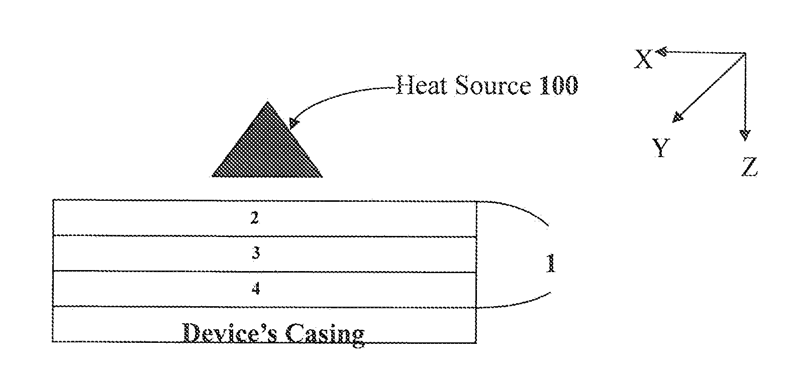
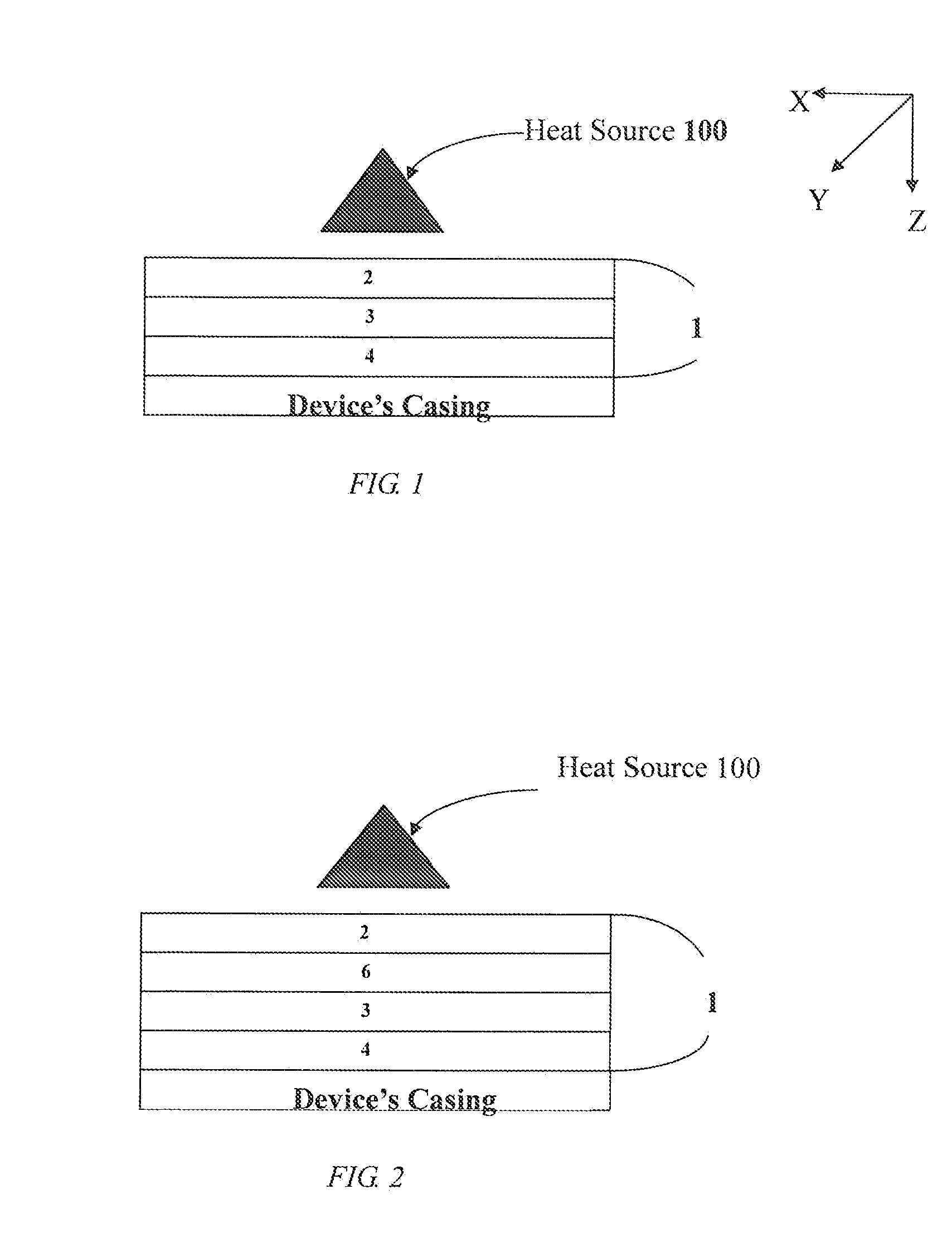
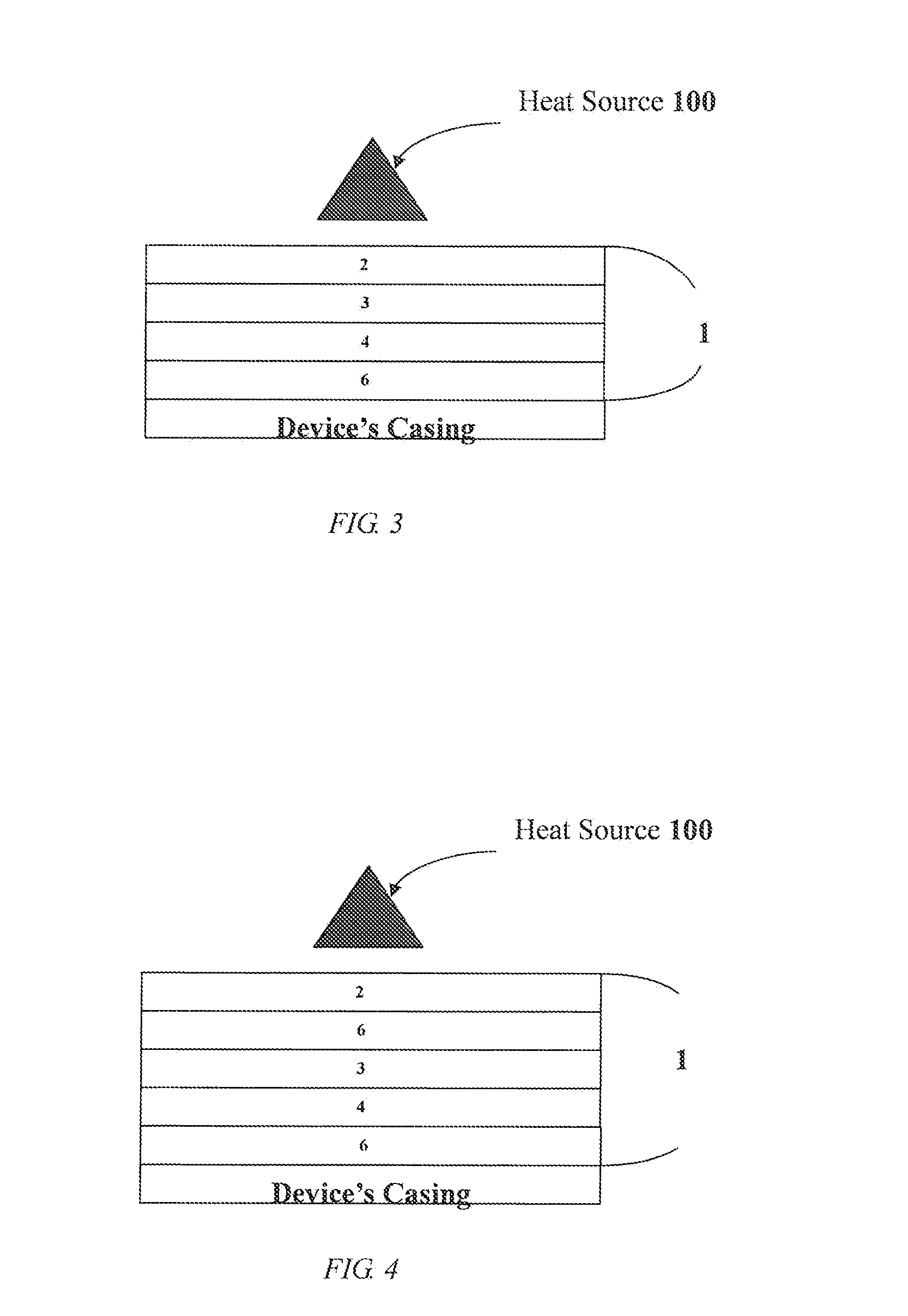
[0056]A computer laptop was modeled for this study and three types of heat dissipation devices were used: a reflective film (Toray E6ZA100, commercially available from Toray, Japan), a flexible graphite sheet electroplated with a metal layer (flexible graphite sheet+metal), and a heat dissipation composite (reflective film+metal+flexible graphite sheet). FIG. 11 illustrates the placement of the heat dissipation device within the computer laptop for this study. In this study, the heat source comprised a copper plate about 10 mm(length)×10 mm(width)×10 mm(height) and 40 mm(length)×40 mm(width)×20 mm(height) in size and a heater (King I Electric Heaters Co, Ltd, Φ6.3 / 110V / 200 W).

[0057]The heat dissipation device was about 100 mm×100 mm in size and interposed between the heat source and the laptop's plastic casing. The study was conducted at room temperature (25° C.)

[0058]The heater was pre-heated to 80° C. prior to the commence...


PUM

PropertyMeasurementUnit
reflectivityaaaaaaaaaa

Abstract

A multi-layer heat dissipation composite for reducing the external surface temperature of an electronic device is disclosed. The heat dissipation composite comprises a reflective component and a component with anisotropic property. The heat dissipation composite further comprises an adhesive. Some embodiments also provide methods for reducing the external surface temperature of an electronic device.

Description

CROSS-REFERENCE TO RELATED APPLICATIONS[0001]This application claims priority to U.S. Provisional Patent Application No. 61 / 669,140, filed Jul. 9, 2012, the contents of which is incorporated herein by reference in its entirety.BACKGROUND OF THE INVENTION[0002]Excessive heat generation caused by the operation of small handheld personal electronic devices, such as cell phones, e-readers and other such devices, is an increasingly challenging problem as the size of such devices continue to shrink, while their performance, and thus heat output, continues to grow. The heat generated by internal electronic components can lead to high external surface temperatures on the outside surface of such devices and result in user discomfort, such as discomfort in a person's lap or palm. Such discomfort can lead to customer complaints, warranty claims and a diminished reputation in the market place. Thus, the thermal management of the sealed electronic enclosures of such devices presents an increasin...

Claims


Application Information

Patent Timeline
Patent Type & Authority Applications(United States)
IPC IPC(8): H05K7/20F28F3/00
CPCF28F3/00H05K7/2039H01L23/3735H01L2924/0002Y10T428/249921H01L2924/00Y10T428/2848A61B6/10G21K1/046
Inventor CHEN, KO-CHUNLIN, CHIU-LANG
Owner WAH HONG INDAL CORP
Why Eureka
Try Eureka