Method for gas metal arc welding

a gas metal arc and welding arc technology, applied in welding/cutting media/materials, welding apparatus, manufacturing tools, etc., can solve the problems of health-threatening welding smoke, vaporisation of wire electrodes, and limited thermal conductivity of welding arc energy that is transferred from the surface to the interior of the wire electrode, etc., to achieve less rigidity, low wear, and adjustment extremely accurately

Inactive Publication Date: 2014-12-04
LINDE AG
View PDF8 Cites 3 Cited by
  • Summary
  • Abstract
  • Description
  • Claims
  • Application Information

AI Technical Summary

Benefits of technology

[0046]The device according to the invention may comprise guidance elements, such as bushings, pipes, rollers or wire guides to move the wire electrode. Such guidance elements are particularly advantageous for large stickouts, to compensate for a curvature of the wire electrode, and to support the wire electrode when it is less rigid due to the effect of the Joulean heating. Such guidance elements are particularly constructed from materials to which weld spatters do not stick, for example ceramic materials among others. In particular, the guidance elements are electrically non-conductive.
[0047]In an advantageous variation, the current contact element has at least one roller, which is in contact with the wire electrode. Particularly the welding current is applied to the wire electrode via said one or more roller. The roller serves as a localised current contact point which, unlike a sliding contact, is of fixed definition and does not change. Sliding contacts are subject to significant wear in conventional GMAW processes due to the relative movement between the wire electrode and the current contact nozzle, so that the conditions of the welding process are changing constantly. Sliding contacts must therefore be replaced frequently. It is very difficult to predict when a current contact will fail. On the other hand, a significant advantage of rollers and rolling contacts is that wear ...

Problems solved by technology

The energy input from the welding arc that is transferred from the surface to the interior of the wire electrode is also...

Method used


Image

  • Method for gas metal arc welding
  • Method for gas metal arc welding
  • Method for gas metal arc welding

Examples


Embodiment Construction

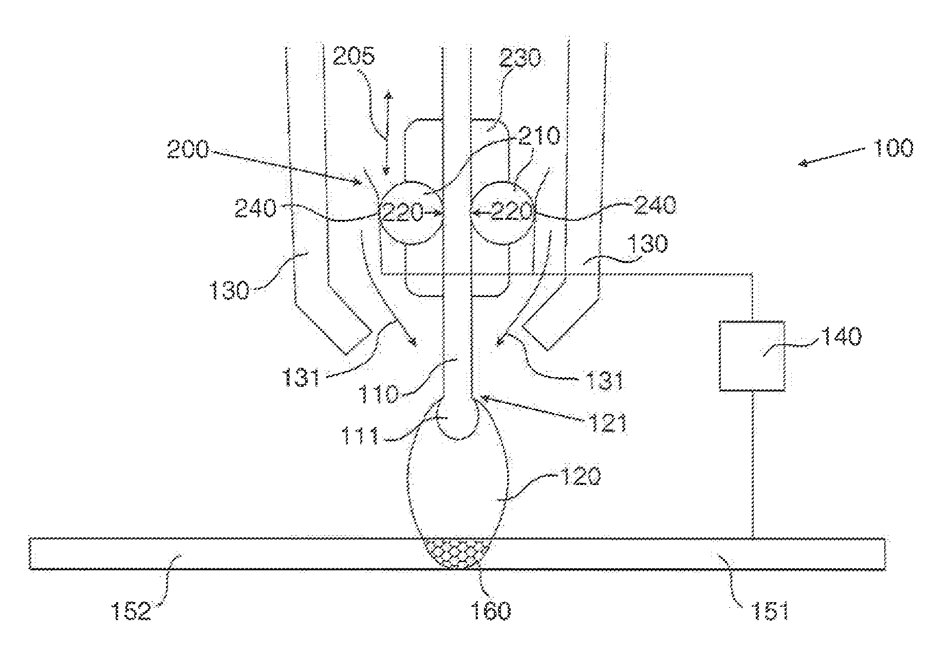
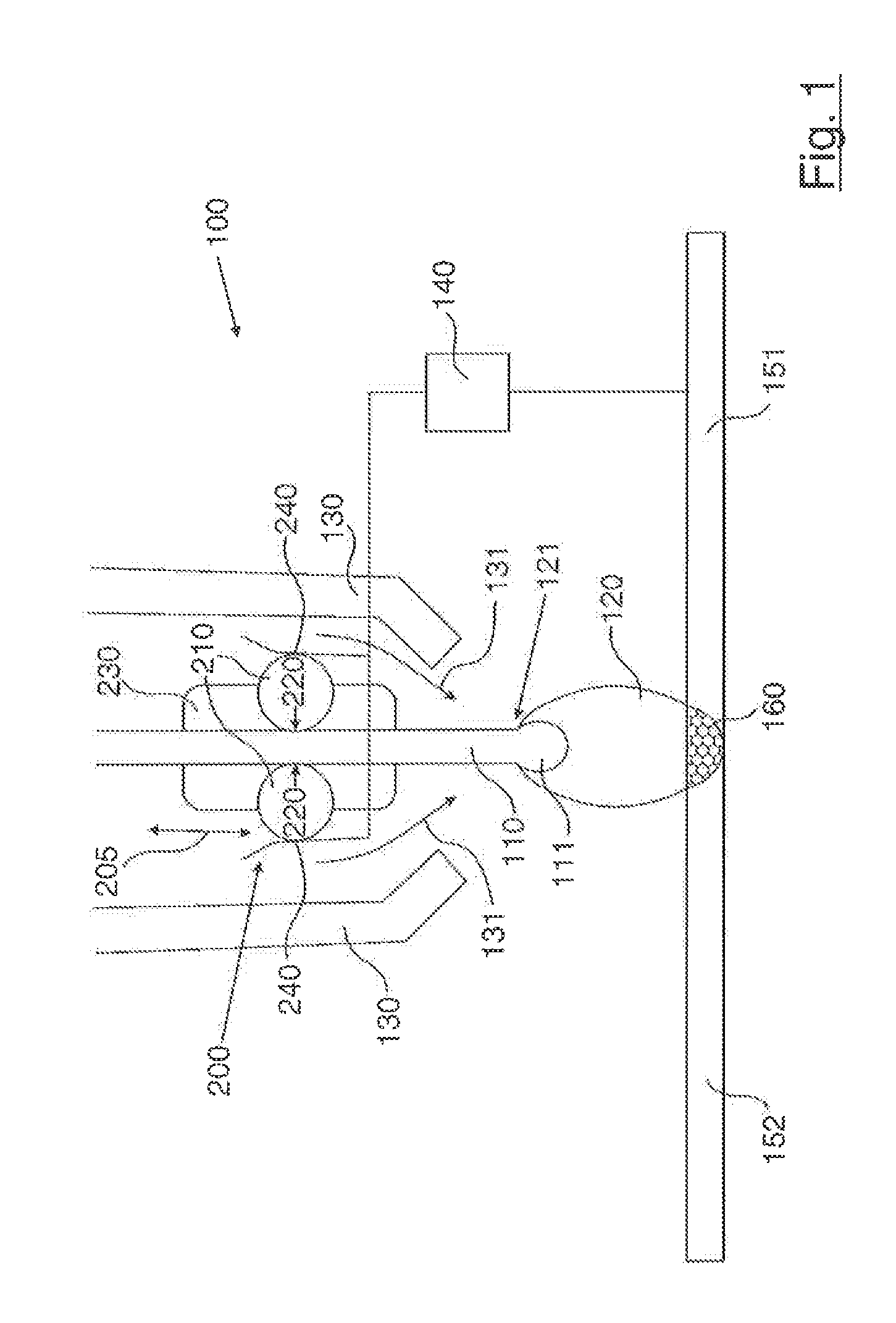
[0059]FIG. 1 is a diagrammatic illustration of a preferred variation of a device according to the invention for gas metal arc welding in the form of a GMAW torch, designated with 100.

[0060]A first workpiece 151 is welded to a second workpiece 152 by means of a joining process using GMAW torch 100. GMAW device 100 comprises a current conducting wire electrode 110 in the form of a wire. GMAW torch 100 comprises a current contact element 200.

[0061]A welding current is applied to wire electrode 110 via current contact element 200. The welding current is supplied by a welding current source 140. Welding current source 140 is connected electrically to current contact element 200 and first workpiece 151 (shown schematically). The welding current causes a welding arc 120 to burn between wire electrode 110 and first workpiece 151.

[0062]A current contact point, through which the welding current flows or is transferred to wire electrode 110, may be adjusted precisely by means of current contac...


PUM

PropertyMeasurementUnit
Lengthaaaaaaaaaa
Lengthaaaaaaaaaa
Poweraaaaaaaaaa

Abstract

A method for gas metal arc welding is disclosed, wherein a welding current is passed through a wire electrode and the a wire electrode is melted by a welding arc, wherein at least one parameter that influences Joulean heating of the wire electrode is adjusted.

Description

CROSS REFERENCE TO RELATED APPLICATIONS[0001]This application claims priority from German Patent Application Serial No. 102013009350.3 filed Jun. 4, 2013 and German Patent Application Serial No. 102013018065.1 filed Nov. 28, 2013.BACKGROUND OF THE INVENTION[0002]The invention relates to a method and a device for gas metal arc welding. In this context, a welding current is passed through a wire electrode and the electrode is melted by a welding arc.[0003]Gas metal are welding (GMAW) is an arc welding method that is used for example in additive welding, or to weld or solder together one, two or more workpieces made from a metal material. In this method, a wire electrode in the form of a wire or strip is fed continuously in a shielded metal gas atmosphere and melted by a welding arc that burns between the workpiece and the wire electrode. In such an instance, the workpiece functions as a second electrode. In particular, the workpiece functions as the cathode, while the wire electrode i...

Claims


Application Information

Patent Timeline
IPC IPC(8): B23K9/10B23K9/09B23K9/173
CPCB23K9/1012B23K9/09B23K9/173B23K9/1093B23K9/123B23K9/295
Inventor SIEWERT, ERWAN
Owner LINDE AG
Why Eureka
Try Eureka