

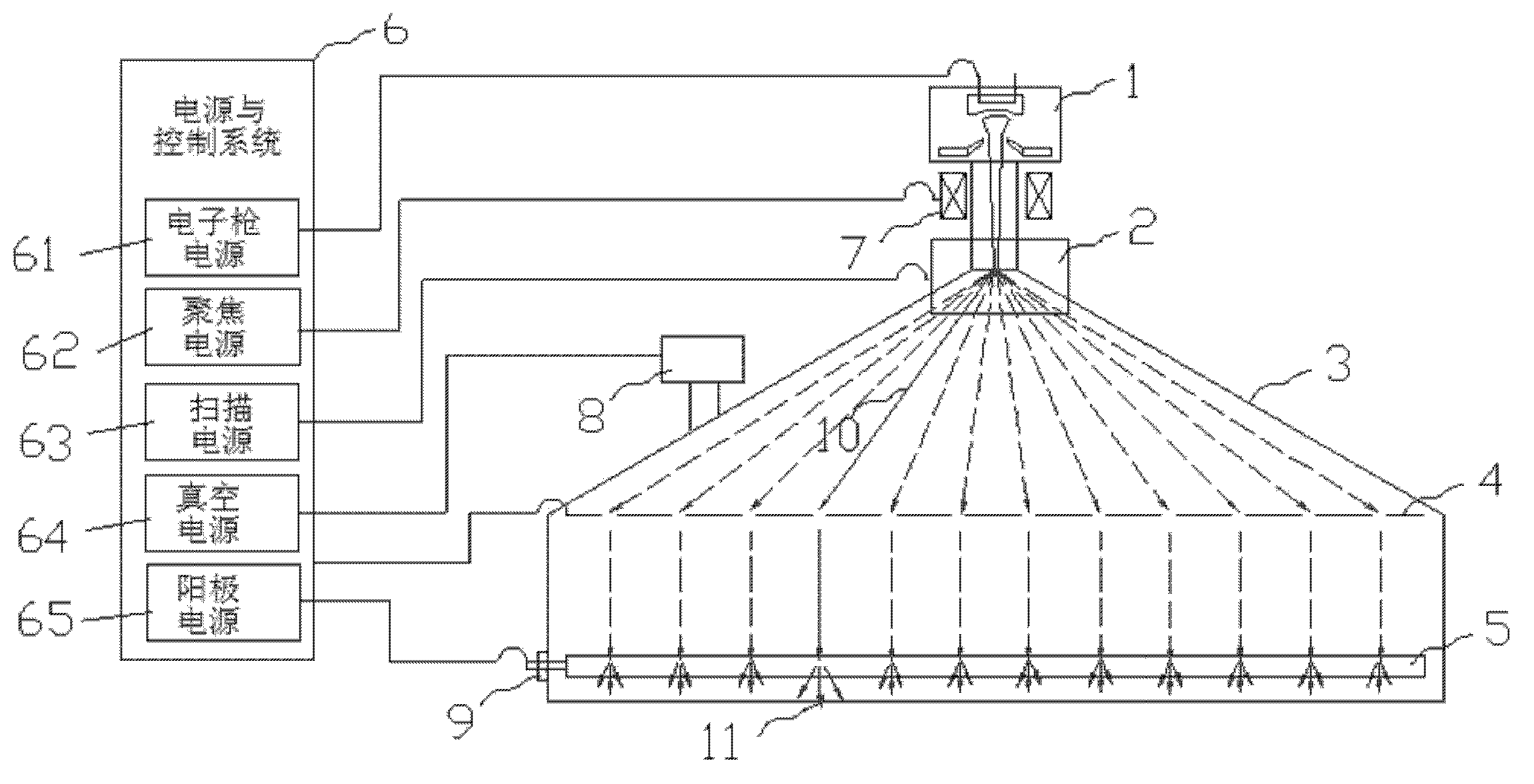
A device and method for generating distributed X rays
An X-ray and distributed technology, applied in the parts of X-ray tubes, X-ray tubes, X-ray tubes, etc., can solve the problems of low emission capability and life of carbon nanotubes, complicated production processes, etc. Ring movement, good repeatability, and the effect of improving inspection efficiency
- Summary
- Abstract
- Description
- Claims
- Application Information
AI Technical Summary
Problems solved by technology
Method used
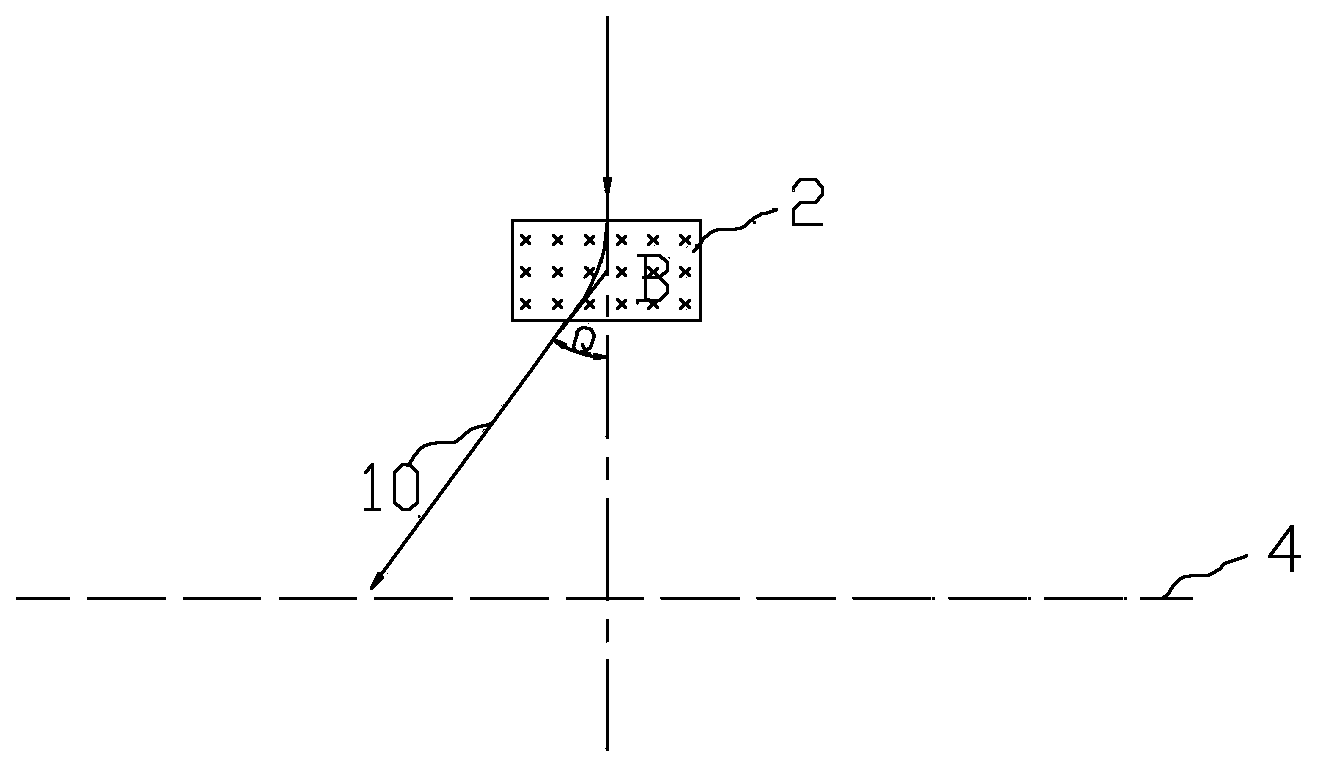
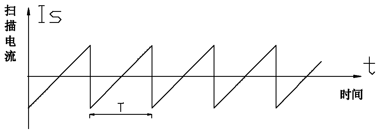
Image

Examples
Embodiment Construction
[0026] Specific embodiments of the present invention will be described in detail below, and it should be noted that the embodiments described here are only for illustration, not for limiting the present invention. In the following description, numerous specific details are set forth in order to provide a thorough understanding of the present invention. It will be apparent, however, to one of ordinary skill in the art that these specific details need not be employed to practice the present invention. In other instances, well-known structures, circuits, materials, or methods have not been described in detail in order to avoid obscuring the present invention.
[0027] Throughout this specification, reference to "one embodiment," "an embodiment," "an example," or "example" means that a particular feature, structure, or characteristic described in connection with the embodiment or example is included in the present invention. In at least one embodiment. Thus, appearances of the p...
PUM
 Abstract
Description
Claims
Application Information