
Display device

a technology of a display device and a display panel, which is applied in the direction of semiconductor devices, instruments, electrical appliances, etc., can solve the problems of reducing the width of the peripheral area, consuming less power, and gradually lighter and thinner display devices, so as to prevent the disconnection of the gate wiring and prevent the change of a characteristic of the thin film transistor

Active Publication Date: 2014-03-13
SAMSUNG DISPLAY CO LTD
View PDF5 Cites 5 Cited by
  • Summary
  • Abstract
  • Description
  • Claims
  • Application Information

AI Technical Summary

Benefits of technology

The present invention is related to a thin film transistor display panel, which includes a flexible film and a top gate structure. The thin film transistor is formed in the same way as a common semiconductor device, preventing disconnection of the gate wiring. Additionally, the display panel is designed to block light generated by the backlight unit, preventing any changes in the thin film transistor's characteristics. The technical effect of this invention is to improve the reliability and stability of the thin film transistor display panel.

Problems solved by technology

Recently, display devices have become gradually lighter and thinner, and consume less power.
However, there may be a limit to the amount that the width of the peripheral area may be decreased because various wirings, driving units, and sealants are attached to the peripheral area of a display panel.

Method used


Image

  • Display device
  • Display device
  • Display device

Examples


Embodiment Construction

[0036]Exemplary embodiments of the present invention will be described in detail with reference to the accompanying drawings.

[0037]In the drawings, the thickness of layers, films, panels, regions, etc., may be exaggerated for clarity. Further, it will be understood that when a layer is referred to as being “on” another layer or substrate, it can be directly on the other layer or substrate, or intervening elements may also be present. Like reference numerals designate like elements throughout the specification.

[0038]As used herein, the singular forms, “a”, “an”, and “the” are intended to include plural forms as well, unless the context clearly indicates otherwise.

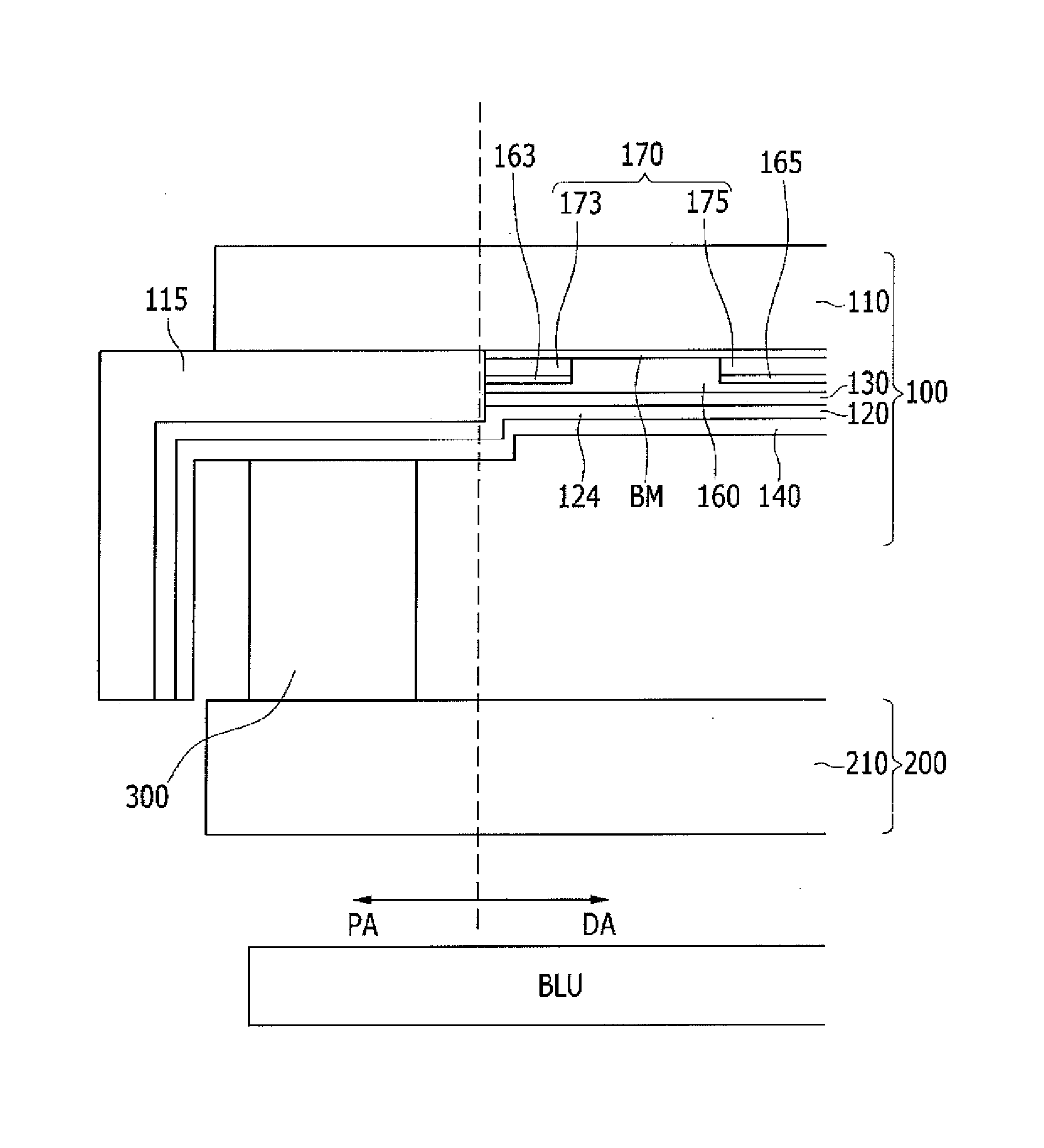
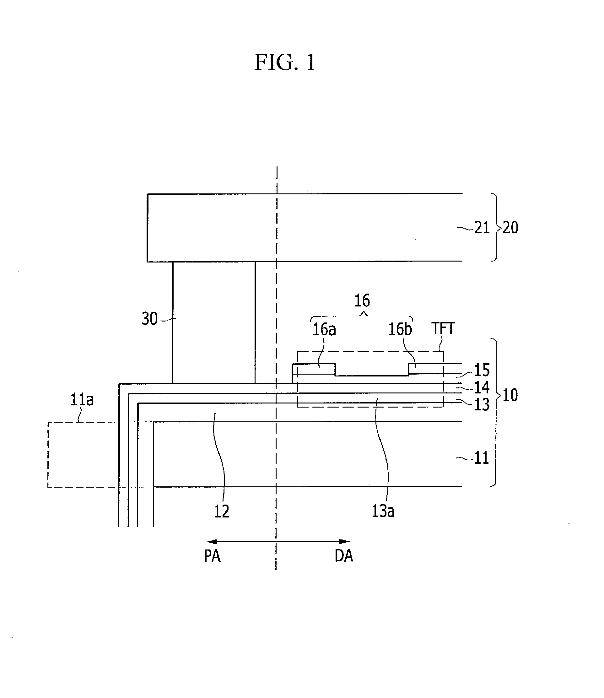
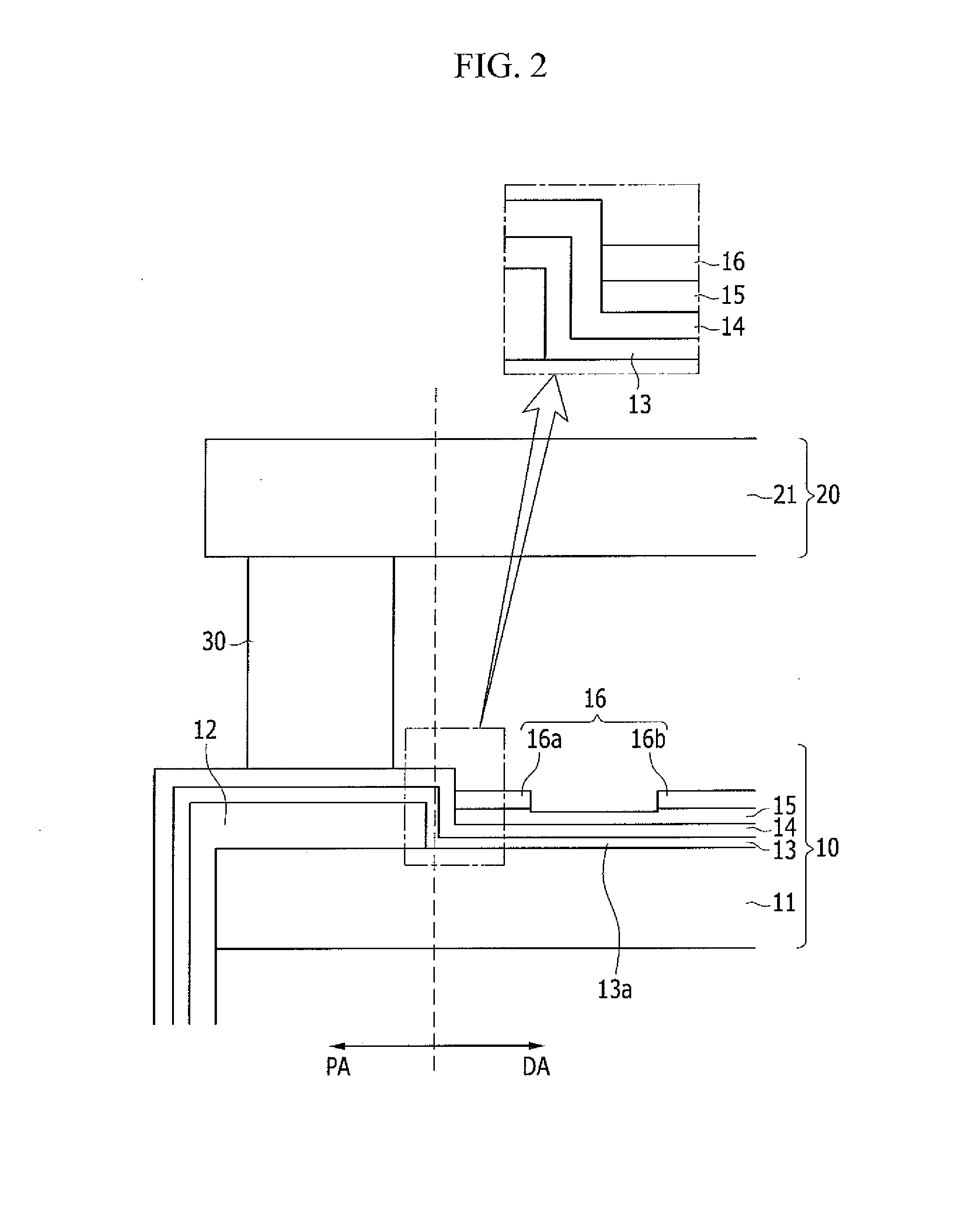
[0039]FIG. 1 is a cross-sectional view illustrating a display device according to a comparative example, and FIG. 2 is a cross-sectional view illustrating a display device according to an exemplary embodiment of the present invention.

First, a first display panel 10 on which a thin film transistor is formed will be described ...


PUM


Abstract

A display device includes: a first display panel including a display area and a peripheral area, a flexible film disposed in the peripheral area, a thin film transistor disposed on the display area while being adjacent to the flexible film, a second display panel facing the first display panel and a sealant disposed in the peripheral area of the first display panel to attach the first display panel and the second display panel, and the first display panel includes: a substrate, a data wiring layer disposed on the substrate and in contact with a side end of the flexible film, a semiconductor layer disposed on the data wiring layer, an interlayer insulating layer disposed on the semiconductor layer and a gate wiring layer disposed on the interlayer insulating layer.

Description

CROSS-REFERENCE TO RELATED APPLICATION[0001]This application claims priority to Korean Patent Application No. 10-2012-0099358 filed on Sep. 7, 2012, the disclosure of which is hereby incorporated by reference herein in its entirety.TECHNICAL FIELD[0002]The present disclosure relates to a display device.DISCUSSION OF THE RELATED ART[0003]A liquid crystal display is one of the currently most widely used flat panel displays, and includes two display panels in which electric field generation electrodes, such as, for example, a pixel electrode and a common electrode, are formed, and a liquid crystal layer interposed therebetween.[0004]An electric field is generated in the liquid crystal layer by applying a voltage to the electric field generating electrode, orientation of liquid crystal molecules is determined through the generated electric field, and polarization of incident light is controlled, so that an image is displayed.[0005]In addition, a flat display device includes, for example...

Claims


Application Information

Patent Timeline
Patent Type & Authority Applications(United States)
IPC IPC(8): H01L27/15
CPCH01L27/15G02F1/1345G02F1/13685G02F1/1333G02F1/1368G02F1/1339H10K59/00
Inventor KIM, YOUNG GUSUNG, BYOUNG-HUNJEON, BAEK KYUNJUNG, JIN-SOO
Owner SAMSUNG DISPLAY CO LTD
Learn More