Bumper

a bumper and bumper technology, applied in the field of bumpers, can solve the problems of bumpers having problems in the total energy absorption amount and productivity, and achieve the effects of preventing temperature rise, superior productivity, and easy manufacturing in very short tim

Inactive Publication Date: 2014-03-13
ASTEER
View PDF4 Cites 20 Cited by
  • Summary
  • Abstract
  • Description
  • Claims
  • Application Information

AI Technical Summary

Benefits of technology

[0020]According to the present invention, the reinforcement beam crashes or plastically deforms at the unquenched portions. This causes the quenched portion sandwiched by the unquenched portions to displace backward together with the left and right ends of the beam. According to this deforming, displacing amount becomes smaller than that of a bumper of prior art in which the reinforcement beam buckles and protrudes to backward. Further, according to the present invention, the total energy absorption amount becomes large and the reinforcement beam is prevented from displacing backward because the reinforcement beam smoothly plastically deforms or crashes without ripping from the unquenched portions.
[0021]According to the present invention, it does not take long time to form the unquenched portions because the unquenched portions are formed by chilling or preventing a temperature from rising. The bumper of the present invention is superior in productivity because it is easily manufactured in very short time

Problems solved by technology

As mentioned above, known bumpers have problems in the total energy absorption amount and the productivity.

Method used


Image

  • Bumper
  • Bumper
  • Bumper

Examples


Embodiment Construction

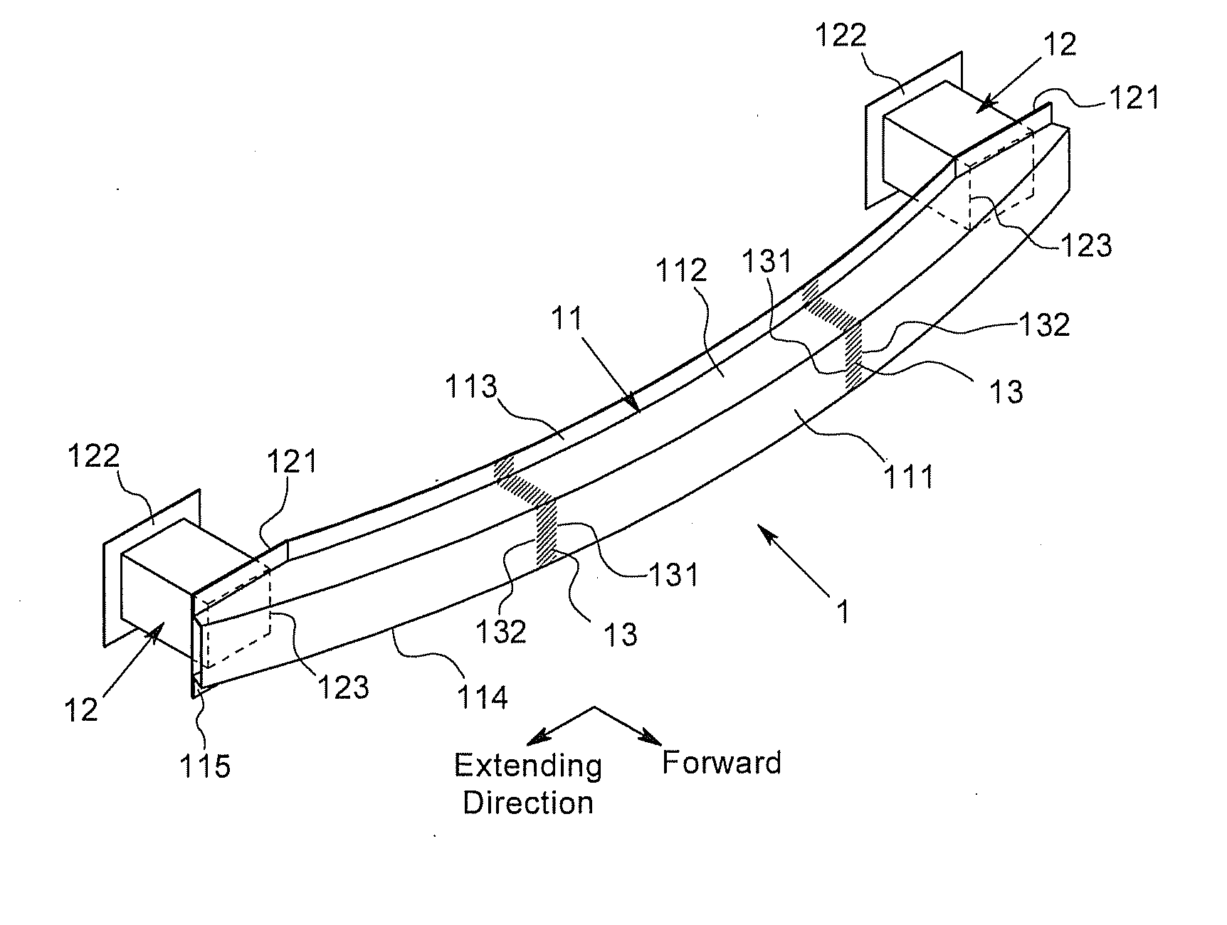
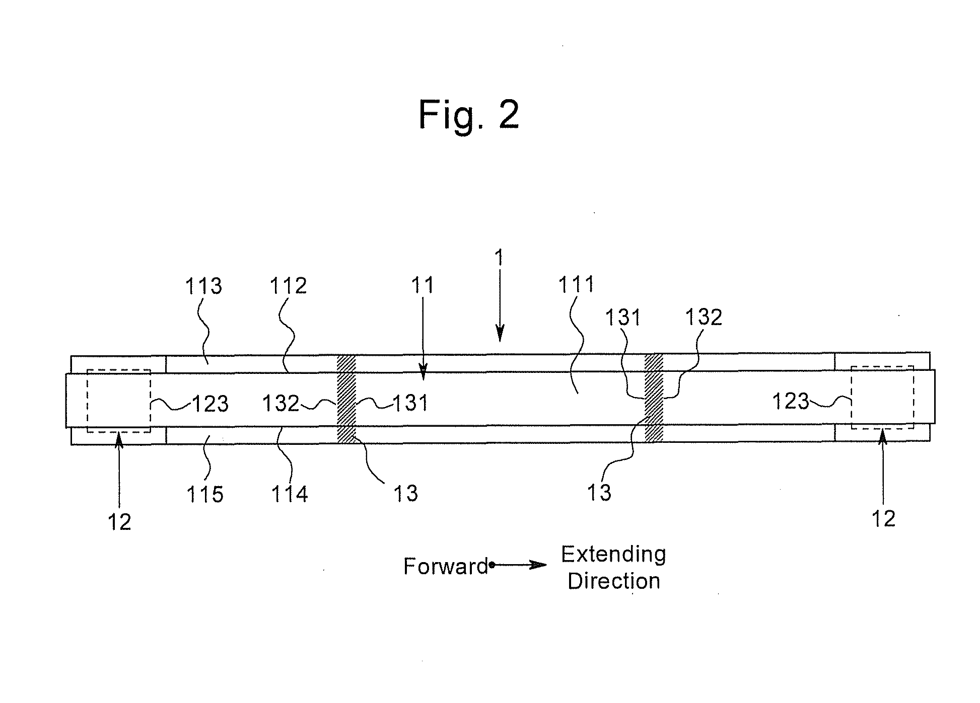
[0029]Preferred embodiments of the present invention is explained with reference to Figures. One example of the bumper of the present invention is illustrated in FIGS. 1 to 4. The bumper 1 of the present example is mounted on a front end of a vehicle. The bumper 1 may be mounted on a rear end of a vehicle. Forward and backward are interchanged in case the bumper 1 is mounted on the back end of the vehicle. The bumper 1 of the present example includes a reinforcement beam 11 made of steel and a pair of support members 12,12 protruding from a vehicle frame 3, which is illustrated in FIG. 4 with a two dot chain line. The pair of support members 12,12 supports the reinforcement beam 11 therebetween. The reinforcement beam 11 is totally quenched except for a pair of unquenched portions 13,13. The bumper 1 is connected to the vehicle frame 3 via a pair of connecting flanges 122,122 provided at backend of the pair of support members 12,12.

[0030]The reinforcement beam 11 includes a front fa...


PUM

PropertyMeasurementUnit
widthaaaaaaaaaa
lengthaaaaaaaaaa
lengthaaaaaaaaaa

Abstract

A bumper for vehicles having a high productivity and a large energy absorption amount in which the reinforcement beam is prevented from buckling. The bumper includes a reinforcement beam made of steel and support members protruding from a vehicle frame and supporting the reinforcement beam therebetween. The reinforcement beam is provided with a quenched portion provided at least over a portion where an obstacle hits the reinforcement beam. The reinforcement beam is further provided with unquenched portions next to the portion where the obstacle hits the reinforcement beam to sandwich the quenched portion. A mechanical strength of the unquenched portions is smaller than the mechanical strength of the quenched portion.

Description

BACKGROUND OF THE INVENTION[0001]1. Field of the Invention[0002]The present invention relates to a bumper for vehicles including a reinforcement beam made of steel and support members. The support members protrude from a vehicle frame and support the reinforcement beam therebetween.[0003]2. Description of the Related Art[0004]A bumper is, for example, provided at a front end or a back end of a vehicle. The bumper absorbs an impact energy when the vehicle collides with an object. A bumper configured by a reinforcement beam which is totally quenched and supporting members supporting the reinforcement beam therebetween is proposed. This kind of bumpers absorbs the impact energy by plastically deforming or crashing the reinforcement beam or the supporting members. Since a force-stroke curve and a total impact energy absorption amount change in accordance with how the reinforcement beam deforms or crashes, a structure of the reinforcement beam is researched as in JPH08-20297 A and JP2007...

Claims


Application Information

Patent Timeline
Patent Type & Authority Applications(United States)
IPC IPC(8): B60R19/03C21D1/18
CPCC21D1/18B60R19/03B60R19/18B60R2019/1826C21D1/673C21D2221/02C21D2221/10
Inventor SHIMOTSU, KOJI
Owner ASTEER
Why Eureka
Try Eureka