Method and apparatus for stabalizing power on an electrical grid using networked distributed energy storage systems

a technology of distributed energy storage and power generation, applied in emergency power supply arrangements, load forecasting in ac networks, transportation and packaging, etc., can solve the problems of high energy cost for users, high cost of energy storage mediums, especially battery energy storag

Active Publication Date: 2014-03-13
STEM
View PDF5 Cites 122 Cited by
  • Summary
  • Abstract
  • Description
  • Claims
  • Application Information

AI Technical Summary

Benefits of technology

[0026]Embodiments of the invention may further provide a method of controlling energy transferred between an electric grid and an electric load location comprises monitoring a first rate of energy transfer from an electric power line to the electric load location, wherein the electric power line is coupled to an electric meter adapted to determine power transferred between the electric load location and the electric grid, receiving a first set of operating parameters that are created based on one or more received external inputs and, based on the first set of operating parameters, varying the energy transfer from an energy source to the electric power line to cause the first rate of energy transfer to remain below a threshold value, wherein the threshold value varies with time.

Problems solved by technology

The cost to a utility for generating or purchasing electrical energy increases dramatically during periods of peak use versus periods of off-peak usage.
The higher rates charged during peak usage periods can lead to significantly higher energy costs for the user, especially when the user's period(s) of high demand coincides with or falls within the interval set by the utility as peak hours.
Energy storage mediums, especially battery energy storage, are expensive and, while various techniques are known by which an energy storage system can be used to optimize energy use at a business or home, such techniques are generally inefficient in applying stored energy to effectively control the energy use at an electric load location.
Consequently, an impractical quantity of energy storage mediums are required at an electric load location to realize useful energy arbitrage.
Each of these approaches generally requires an uneconomical amount of energy storage capacity in order to offset demand peaks at the electric load location.
Furthermore, use of a single demand set-point typically results in an energy storage system running out of energy storage availability due to over-reaction of the controlling components to the demand set point set by the controlling system.
Not only is wind and solar generation unpredictable, but these generators also have no automatic control schemes to help maintain system synchronous speed and no event response capability during their process of delivering power to the grid.
During grid events, such as when there is electricity supply disruption, due to transmission or generation failure or renewable energy source(s) variability, electricity generation from the power generators can become out of step, or sync.
The lack of synchronization can both be due to the time it takes for power to travel over long distances and the different speeds at which generators respond to meet these demand and supply changes.
Therefore, the relative power angle (e.g., angular difference in the phasor angles of voltages at different points along a transmission system) becomes out of sync across geographically disparate areas, and power oscillations occur.
The power oscillations create swings in the amount of power cycling back and forth on the transmission and distribution lines that can both damage transmission and distribution equipment and create additional energy losses in the power lines, thereby de-rating the grid's transmission capacity.
While oscillation in the power flow in the grid does occur after the first grid event, the amount of power fluctuation is not significant enough to cause large fluctuations in the power flowing in the electric grid.
However, one will note that the second grid event (e.g., Event 2) causes a much larger drop in power flowing through the electric grid which causes larger undamped oscillations to occur in the electric grid, as the power generator attached to the electric grid try to correct for the drop in power transmission through the grid.
Typically, these power oscillations cannot be measured at a single node on the grid, and thus require multiple measurement nodes to determine the oscillation.
It is believed that the undesirable effect of having the relative power angles from two or more power generators being out of sync becomes a larger issue when moderate to large power fluctuations occur within the grid (e.g., oversupply or undersupply situations caused by a grid event).
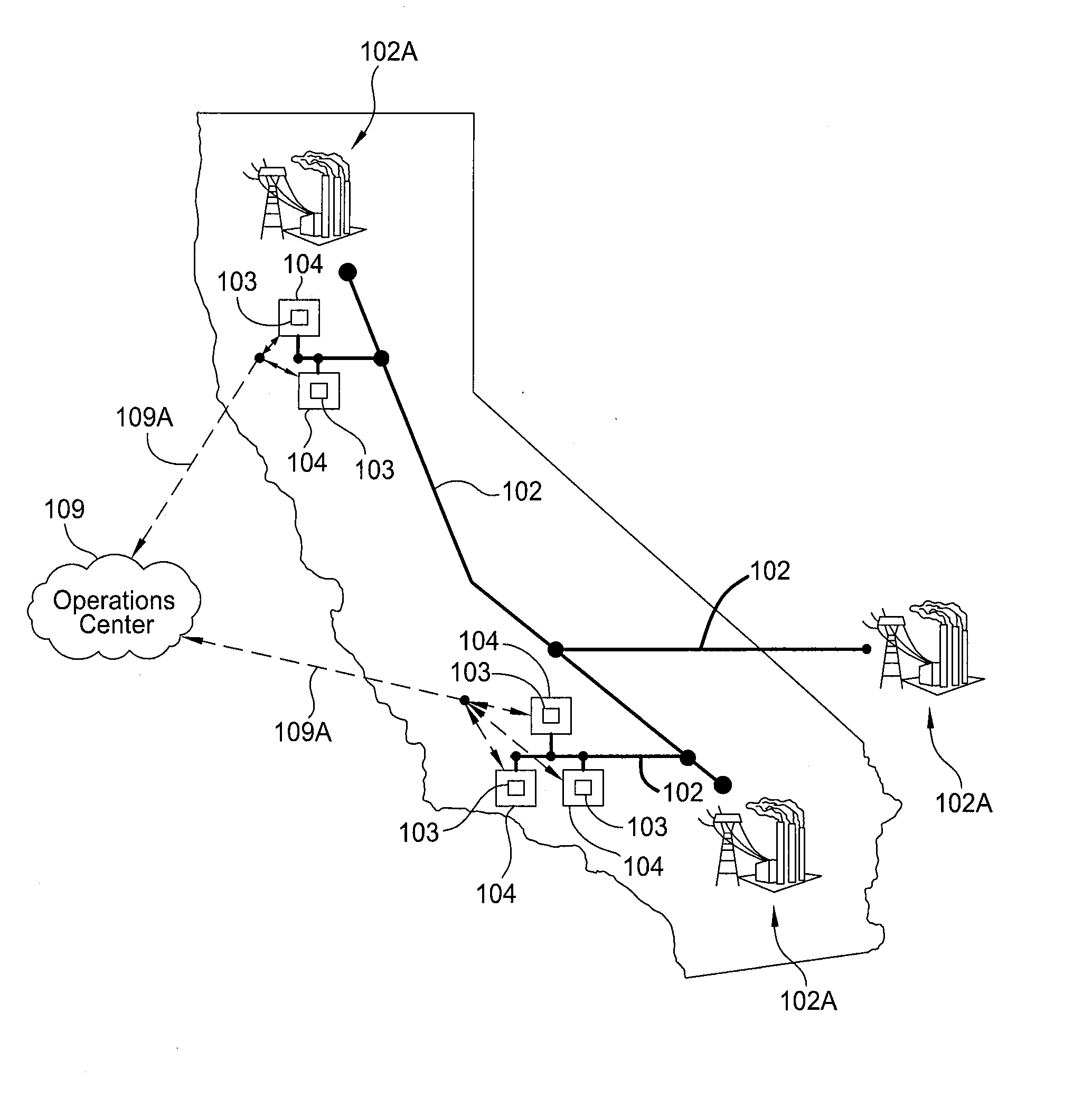
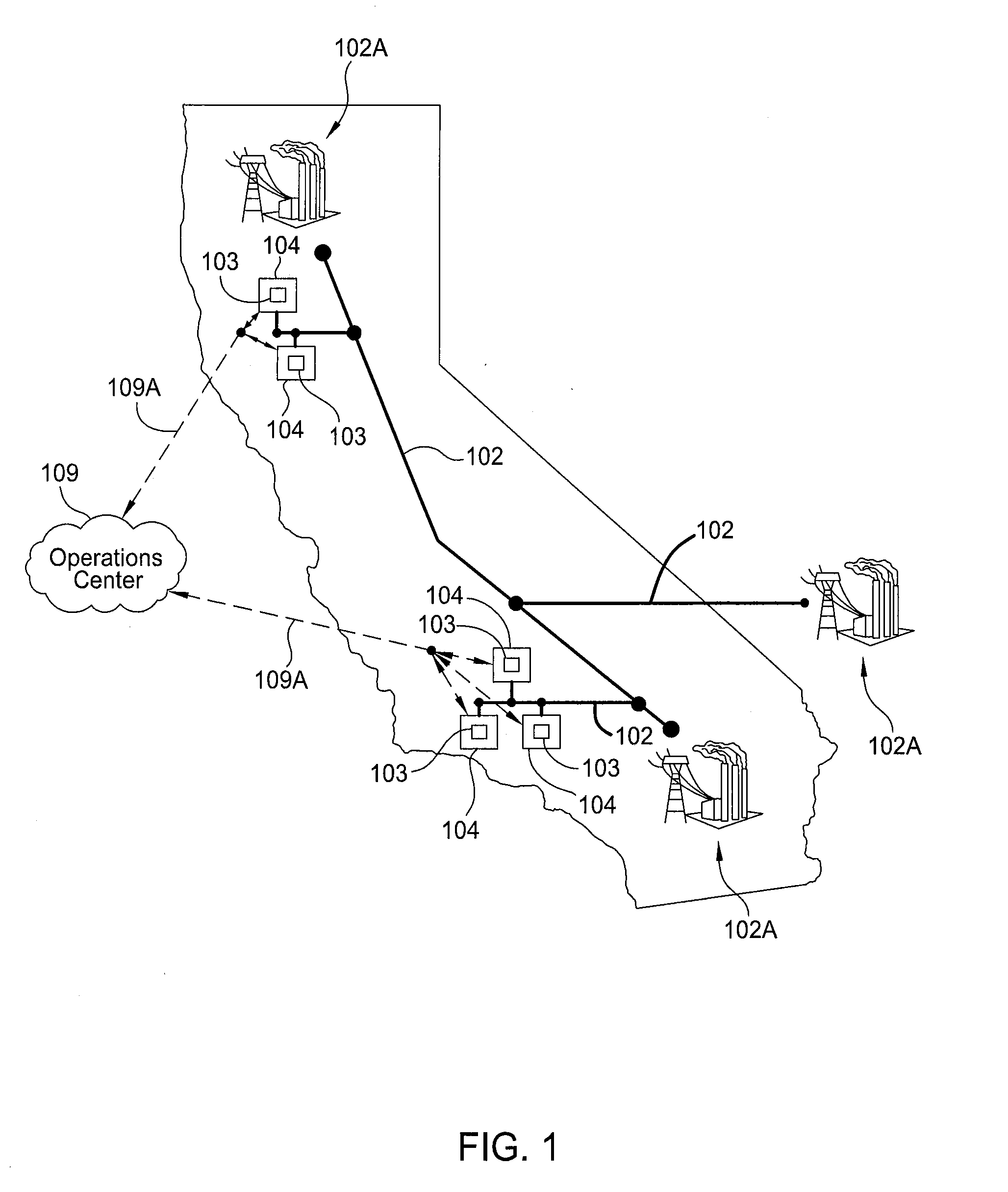
California's transmission grid has several transmission lines with constant power oscillations, some of which cause the transmission operator to place significant restrictions on transmission line capacity (e.g., restrictions on the power delivery).
This, in turn, restricts the import of clean and inexpensive hydropower from the Pacific Northwest, for example.
As an example, if Los Angeles experiences a large load in the late afternoon of a hot day and a nearby power plant or transmission line fails, then there is a sudden undersupply scenario in the power distribution and transmission grid in Southern California.
Then both the local and Northwest power generators respond to meet the increased power demand created by the power plant failure, but the generators in the Northwest are generally relatively slower to respond, due to electrical transmission delays and the nature of the power generating devices used to supply power to the grid.
The difference in the timing of the delivery of power from the local and Northwest power generators then creates an oversupply situation in Southern California, as both power generators try to compensate for the variation in the power demand.
Therefore, again, an undersupply situation occurs as both generators try to compensate for the over-supply situation.
Greater occurrences of these power swings and instability in the delivery of power through the various grid distribution and transmission lines have been happening more frequently across the US.
There is a belief that the addition of renewable energy source will cause the electric grid to become more unstable as more conventional synchronous generation are displaced by the variable power generation created by most renewable energy sources.
Moreover, today's electric power grid is also increasingly threatened by variable electricity demand and the addition of intermittent supply from many different types of power generators, such as renewable energy power generators, fast acting natural gas power generators and fossil fuel power generators.
The fluctuating supply of power in the electric grid creates issues for the electric grid equipment originally designed to balance slower-changing load / demand and supply.
Mechanically actuated equipment like load tap changing transformers (LTCs), voltage regulators, and switched capacitors are unable to switch fast enough or often enough in order to support or compensate for this variability.
Their mechanical nature results in equipment that is not able to meet the needs of today's changing electric grid design.
The increased variability will result in utility equipment having shorter lifespan and utility customer's equipment being damaged more frequently as voltage, current and / or power fluctuations become uncontrollable and exceed acceptable tolerances.

Method used


Image

  • Method and apparatus for stabalizing power on an electrical grid using networked distributed energy storage systems
  • Method and apparatus for stabalizing power on an electrical grid using networked distributed energy storage systems
  • Method and apparatus for stabalizing power on an electrical grid using networked distributed energy storage systems

Examples


Embodiment Construction

[0061]Embodiments of the present invention include control methods employed in multiphase distributed energy storage systems that are located behind utility meters typically located at, but not limited to, medium and large commercial and industrial locations and / or are connected along various parts of an electric grid. These distributed energy storage systems can operate semi-autonomously, but each may be in frequent contact with a cloud-based optimization engine that is configured to develop energy control solutions based on various data inputs and to communicate these energy control solutions to the distributed energy storage systems. Each installed distributed energy storage system can be used to monitor or receive information about the electricity use at its specific location and information relating to the power transmission and distribution on the electric grid. In an effort to control the local demand, the distributed energy storage system can discharge at times of high deman...


PUM


Abstract

Embodiments of the present invention include control methods employed in multiphase distributed energy storage systems that are located behind utility meters typically located at, but not limited to, medium and large commercial and industrial locations. These distributed energy storage systems can operate semi-autonomously, and can be configured to develop energy control solutions for an electric load location based on various data inputs and communicate these energy control solutions to the distributed energy storage systems. In some embodiments, one or more distributed energy storage systems may be used to absorb and/or deliver power to the electric grid in an effort to provide assistance to or correct for power transmission and distribution problems found on the electric grid outside of an electric load location. In some cases, two or more distributed energy storage systems are used to form a controlled and coordinated response to the problems seen on the electric grid.

Description

CROSS-REFERENCE TO RELATED APPLICATIONS[0001]This application claims the benefit of U.S. Provisional Patent Application Ser. No. 61 / 720,940, filed Oct. 31, 2012 [Atty. Dkt. No. STEM / 0015L], this application is also a continuation-in-part of U.S. patent application Ser. No. 14 / 061,643, filed Oct. 23, 2013 [Atty. Dkt No. STEM / 0014], which claims the benefit of U.S. Provisional Patent Application Ser. No. 61 / 717,528, filed Oct. 23, 2012 [Atty. Dkt. STEM / 0014USL], and is a continuation-in-part of U.S. patent application Ser. No. 14 / 026,993, filed Sep. 13, 2013 [Atty. Dkt. No. STEM / 0012], which claims the benefit of U.S. Provisional Patent Application Ser. No. 61 / 700,840, filed Sep. 13, 2012 [Atty. Dkt No. STEM / 0012L] and U.S. Provisional Patent Application Ser. No. 61 / 801,274, filed Mar. 15, 2013 [Atty. Dkt No. STEM / 0016L], which are all hereby incorporated herein by reference.BACKGROUND OF THE INVENTION[0002]1. Field of the Invention[0003]Embodiments of the present invention generally ...

Claims


Application Information

Patent Timeline
Patent Type & Authority Applications(United States)
IPC IPC(8): H02J3/24
CPCH02J3/24H02J3/32Y04S10/30Y04S20/12Y04S40/124Y04S40/126H02J7/0071H02J3/003H02J2203/20H02J13/00002H02J13/00017H02J13/00016H02J13/00026H02J13/00034Y02B90/20Y02E60/00Y04S40/20Y04S10/50H02J7/04H02J13/00022H02J3/00
Inventor DETMERS, JAMES W.KEARNS, BENBURLINSON, JONSTEVENS, DREW
Owner STEM
Why Eureka
Try Eureka