Lighting device for identifying and marking traffic areas of airports

a technology for airports and lighting devices, applied in the direction of traffic control systems, instruments, electrical equipment, etc., can solve the problems of increasing the weight of lighting devices, requiring additional transformers, and consuming a relatively large amount of power during their operation

Active Publication Date: 2014-03-13
INDUPERM
View PDF3 Cites 26 Cited by
  • Summary
  • Abstract
  • Description
  • Claims
  • Application Information

AI Technical Summary

Benefits of technology

[0012]In a preferred embodiment, the activation circuit has a temperature detection means, which is capable of detecting the temperature of the at least one semiconductor lamp. By measuring the temperature of the semiconductor lamp, which is provided to the contr...

Problems solved by technology

A further disadvantage of halogen lamps is that they consume a relatively large amount of power during their operation.
One disadvantage of the lighting devices, of the related art, used for identifying and marking traffic areas of airports is that an additional transformer is required to adapt the control circuit (provided for the operation of the at least one semiconductor element) to the supply ...

Method used


Image

  • Lighting device for identifying and marking traffic areas of airports
  • Lighting device for identifying and marking traffic areas of airports

Examples


Embodiment Construction

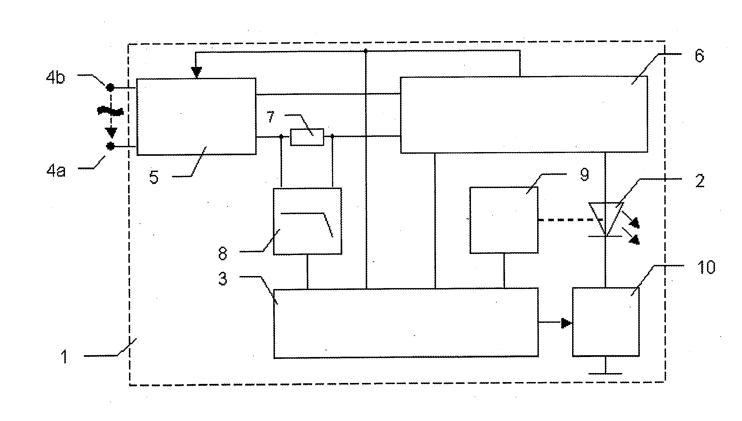
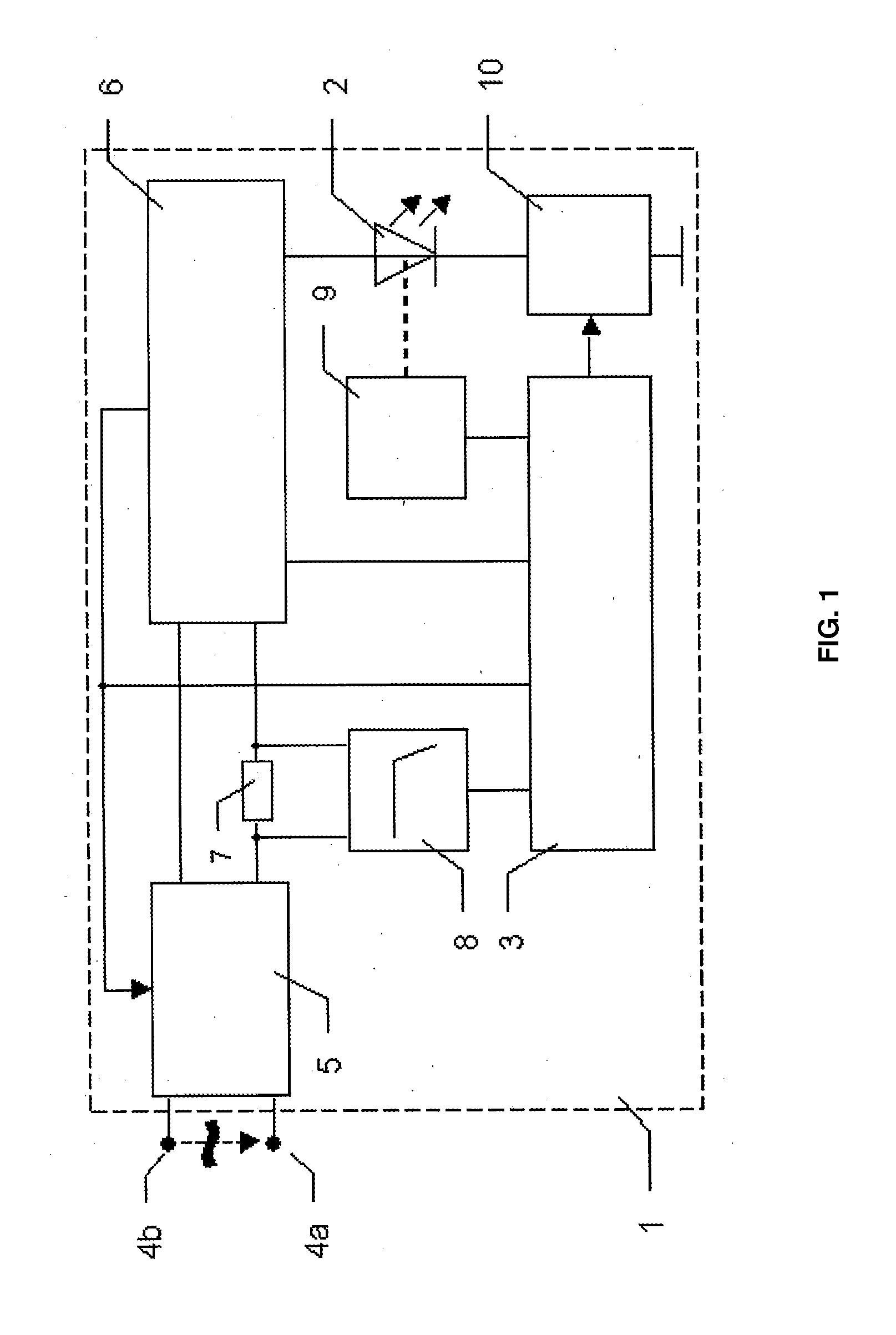
[0016]FIG. 1 shows a schematic circuit of an embodiment of the lighting device. In this exemplary embodiment, the lighting device 1 comprises a semiconductor lamp or light source 2, which preferably includes a light-emitting diode (LED), and an electronic control circuit for activating the semiconductor lamp 2. The electronic control circuit has two terminal means 4a, 4b, with the aid of which the lighting device 1 is connectable to an electrical AC supply network. Furthermore, the electronic control circuit has a rectifier means 5, an internal power supply device 6, which is connected to the rectifier means 5, for supplying the semiconductor lamp 2 with electric direct current, and a central control unit 3. The central control unit 3 preferably includes a microcontroller or an application-specific electronic circuit. The rectifier means 5 is preferably implemented as a synchronous rectifier means, but can include other known rectifier arrangements. The internal power supply device ...


PUM


Abstract

A lighting device, capable of identifying and marking traffic areas of airports, comprises at least one semiconductor lamp and an electronic control circuit, which is connectable to an electrical AC supply network with constant current feed. For controlling the operation of the semiconductor lamp, the control circuit has a rectifier, which is connectable without a transformer to the electrical AC supply network. It further has an internal power supply, which is connected to the rectifier, for supplying the semiconductor lamp with an electric direct current. Furthermore, the voltage supply device (3) having electronic power factor correction means, by means of which voltage and current can be kept in phase in all operating states of the lighting device (1). It furthermore re-adjusts the input voltage from the electrical AC supply network to allow the current predefined on the AC supply network to flow in the event of a small power demand of the electronic control circuit.

Description

CROSS-REFERENCE TO RELATED APPLICATIONS[0001]This application is a continuation of the pending International patent Application No. PCT / EP2011 / 052975 filed on Mar. 1, 2011, which designates the United States and claims priority from and benefit of the European Patent Application No. 10155012.7 filed on Mar. 1, 2010. Disclosure of each of the above-mentioned patent applications is incorporated herein by reference in its entirety.TECHNICAL FIELD[0002]The invention relates to a lighting device for identifying and marking traffic areas of airports such as, for example, runways, landing strips, and taxiways.BACKGROUND ART[0003]Lighting devices, which are capable of identifying and marking traffic areas of airports and emitting signals, have been utilized. For example, runways and landing strips as well as taxiways of airports have been employing lighting devices that can mark, for example, the beginning, the end, and the middle of a runway and, optionally, individual sections of the runw...

Claims


Application Information

Patent Timeline
IPC IPC(8): B64F1/20B64F1/00H05B44/00
CPCB64F1/002B64F1/20H05B47/10
Inventor RUPPRATH, BERNHARDDECIUS, NIKOLAUSABEL, BJORN
Owner INDUPERM
Why Eureka
Try Eureka