Multiple paths measuring and imaging apparatus and method

a multi-path measuring and imaging apparatus technology, applied in the field of optical interferometers, can solve the problems of complex configuration, inability to reconfigure in terms of functionality, and inability to easily adjust the delay of optical signals,

Inactive Publication Date: 2014-03-13
UNIVERSITY OF KENT
View PDF2 Cites 32 Cited by
  • Summary
  • Abstract
  • Description
  • Claims
  • Application Information

AI Technical Summary

Benefits of technology

[0018]In a first aspect, the present invention discloses optical interferometer configurations that can provide interference along parallel optical delays. Such configurations ...

Problems solved by technology

Such a configuration presents the following disadvantages: (i) different states of polarization cannot be associated with unique carrier frequencies; (ii) in integrated formats, optical delays cannot be easily adjusted; (iii) after passing a train of cascaded interferometers, the intensity in channels corresponding to different carrier frequencies present unequal optical intensities.
As each phase element introduces a separate frequency shift, the configuration is complex and not reconfigurable in terms of functionality.
Such an embodiment has the following disadvantages: (i) employs a single frequency with spectral scanning in time to achieve different delays, a procedure that is time consuming; (ii) different polarization states that cannot be associated with unique carrier frequencies.
Two major causes for failure to achieve more ch...

Method used


Image

  • Multiple paths measuring and imaging apparatus and method
  • Multiple paths measuring and imaging apparatus and method
  • Multiple paths measuring and imaging apparatus and method

Examples


first embodiment

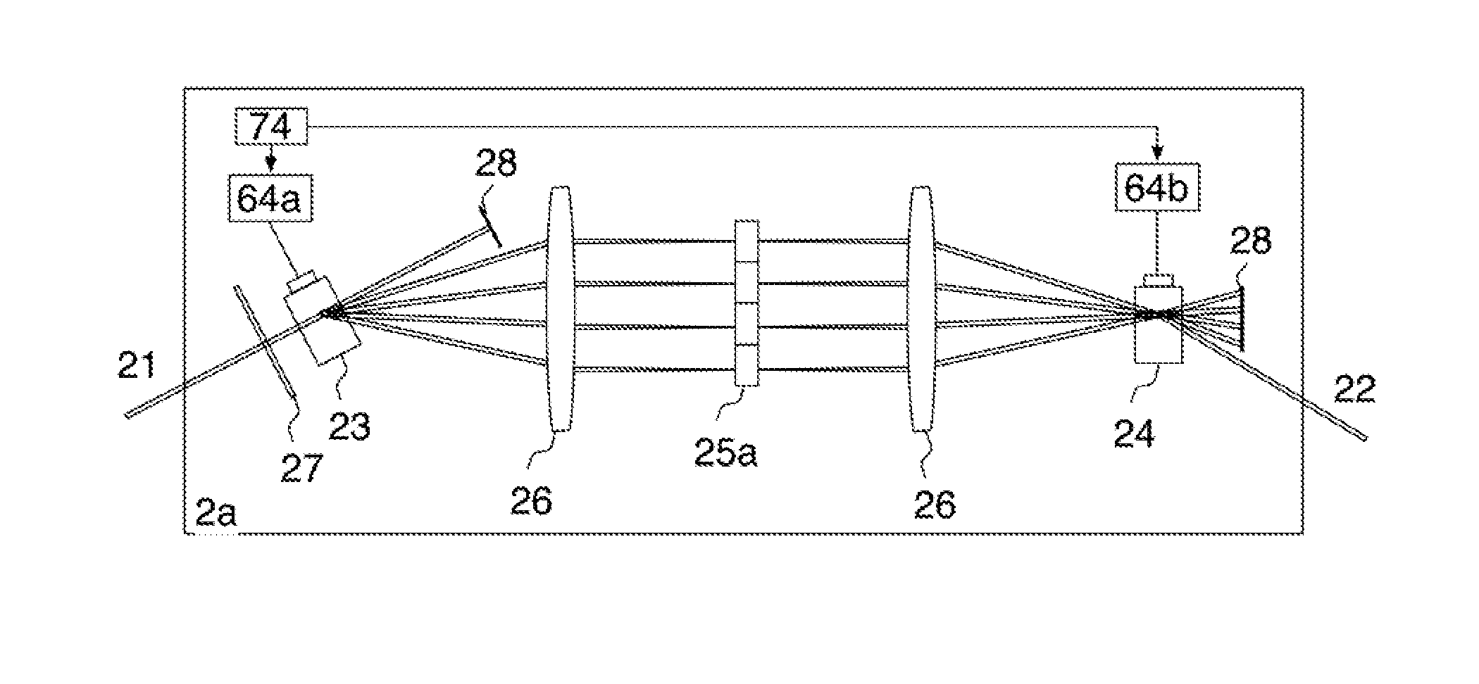
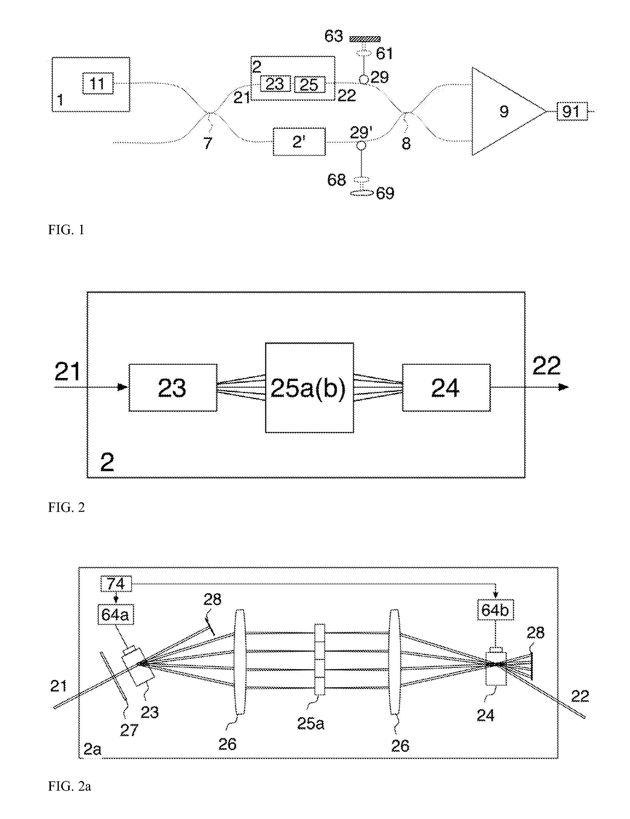
[0074]FIG. 2a discloses the multiplexer using parallel paths. A frequency shifter, 23 is employed, implemented using an acousto-optic modulator (AOM) 23. The RF excitation of the AOM, 23 consists in a number of P radio frequency (RF) signals of different frequencies, fp, provided by a driver 64a. This produces angular spatial separation of P beams, according to the frequency of the signal applied to 23 by the driver 64a. The AOM 23 deflects the input beam 21 into P beams in different directions.

[0075]A first lens 26, placed at a distance equal to its focal length from the AOM 23, redirects the P beams parallel to each other before the multiple phase element 25a. A second lens 26 is positioned at a distance equal to the summation of focal lengths of lens 25 with focal length 26 and behind it, at a distance approximately equal to its focal length, a second AOM element, 24, is placed. The effect of the lens 26 and AOM 24 is to bring all diffracted beams along the same axis after the AO...

third embodiment

[0111]FIG. 4a presents the apparatus according to the invention, where a combination of two multiplexers as disclosed in FIG. 2g are used, consisting of a combination of two different categories of phase elements. Let us say that the ring in the reference arm, 77, is of length LR and the ring in the object arm, 77′, is of length LO and the frequency of signals driving the two frequency shifters 32 and 32′ is FR and FO respectively, and where |FR−FO|=ΔF. The signal at the output of balanced receiver 9 pulsates at a frequency:

νp,m=(2fp−fo)+mΔF.   (4a)

For p=1, the frequencies of the driving signals can be adjusted to make 2f1−fo=0 and for the next values p, the fp+1−fp=δf. (4a) becomes:

νp,m=(p−1)δf+mΔF   (4b)

The frequencies encode signals from depths:

zp,m=|pδ+m(LO−LR)|  (4c)

[0112]The multiple channels produced by such a combination of delaying elements is illustrated in FIG. 4b for P=2 and M=11. The multiple recirculation loops generate more channels than 10, but only the first 11 are ...

fourth embodiment

[0116]A fourth embodiment according to the invention is disclosed in FIG. 5a, where a multiplexer 2h is placed in the reference path, containing multiple parallel shift delays, in the multiple phase element 2b, that are introduced within a recirculation loop. A similar recirculation loop is replicated in the object arm. The frequency shifters 32 and 32′ can be eliminated in this embodiment but amplifiers 33 and 33′ may still be used. The lengths of the two rings 77 and 77′ are respectively LR and LO, where LR is measured along the minimum delay channel in the phase elements array 25.

[0117]The frequencies of the signals applied to the two AOMs in the parallel paths are fp. In the block 2h′, two AOM 23′ and 24′ are shown, to compensate for dispersion of the two AOMs 23 and 24 in the multiplexer 2h. However, a single frequency shifter of total length to that of the AOMs in the reference arm can be used instead. Therefore, for simplicity, we will consider the effect of the two AOMs 23′ ...


PUM


Abstract

The invention discloses an optical interferometer which can be used to provide simultaneous measurements over multiple path lengths and methods to employ such an interferometer as to achieve a variety of functions covering simultaneous measurements at different depths separated by an increment of a multiple differential delay in the interferometer as well as simultaneous polarization measurements from a given depth and imaging. Configurations and methods are presented to encode the axial length in an object under investigation using frequency shifting as well as chirping the frequency of signals determining the frequency shifting. Methods are disclosed on the combination of multiple path configurations as to achieve versatile functionality in measurements, by using either broadband excitation or swept source excitation, combined with either discreet frequency shifting or chirped frequency shifting. Under swept source excitation, the invention discloses a long axial range apparatus, with constant sensitivity.

Description

1. FIELD OF THE INVENTION[0001]The present invention relates to an optical interferometer which can be used to provide simultaneous measurements and simultaneous optical coherence tomography (OCT) images over multiple path lengths, using principles of low coherence interferometry or spectral interferometry.2. BACKGROUND AND PRIOR ART[0002]There is an interest in OCT of speeding up the acquisition to cope with moving targets. Also, in the field of sensing, there is a need to collect data from multiple points simultaneously. The configurations disclosed in patent number U.S. Pat. No. 6,775,007 B2 by Izatt et al. employ versions of cascaded Mach-Zehnder interferometers in conjunction with frequency shifters to create multiple path length differences associated with unique frequencies. Such a configuration presents the following disadvantages: (i) different states of polarization cannot be associated with unique carrier frequencies; (ii) in integrated formats, optical delays cannot be e...

Claims


Application Information

Patent Timeline
IPC IPC(8): G01B9/02
CPCG01B9/0209G01B9/02028G01B9/02091G01B9/02G01B9/02002G01B9/0201
Inventor PODOLEANU, ADRIANZURAUSKAS, MANTASROGERS, JOHN
Owner UNIVERSITY OF KENT
Why Eureka
Try Eureka