Method of clocking a turbine by reshaping the turbine's downstream airfoils
- Summary
- Abstract
- Description
- Claims
- Application Information
AI Technical Summary
Benefits of technology
Problems solved by technology
Method used
Image
Examples
Embodiment Construction
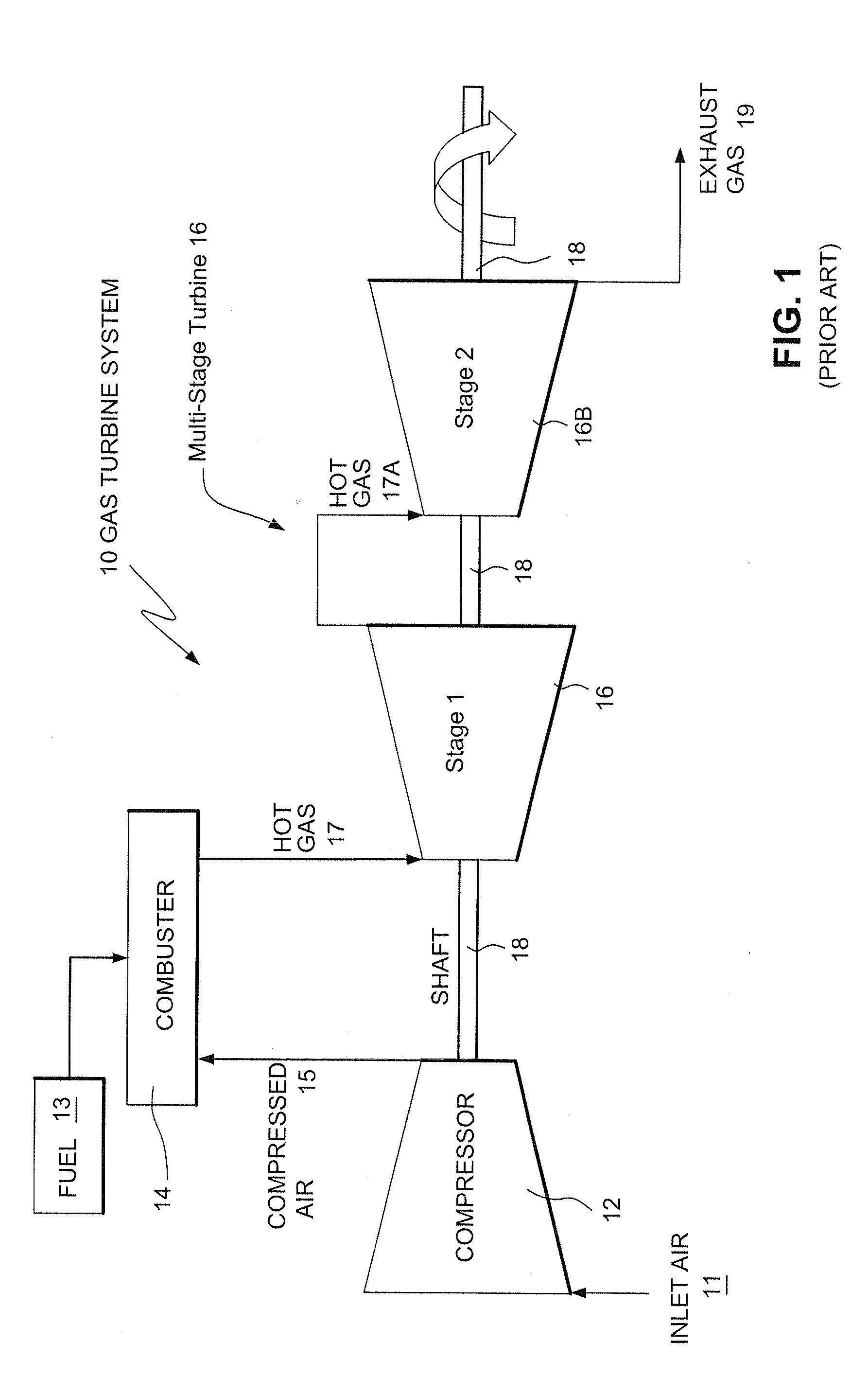
[0024]FIG. 1 is a simplified schematic diagram of a multi-stage gas turbine system 10. The gas turbine system 10 shown in FIG. 1 includes a compressor 12, which compresses incoming air 11 to a high pressure, a combustor 14, which burns fuel 13 so as to produce a high-pressure, high-velocity hot gas 17, and a turbine 16, which extracts energy from the high-pressure, high-velocity hot gas 17 entering the turbine 16 from the combustor 14 using turbine blades (not shown in FIG. 1) that are rotated by the hot gas 17 passing through them. As the turbine 16 is rotated, a shaft 18 connected to the turbine 16 is caused to be rotated as well. As shown in FIG. 1, turbine 16 is a multi-stage turbine with the first and second stages shown and designated as 16A and 16B, respectively. To maximize turbine efficiency, the hot gas 17 / 17A is expanded (and thereby reduced in pressure) as it flows from the first stage 16A of turbine 16 to the second stage 16B of turbine 16, generating work in the differ...
PUM
| Property | Measurement | Unit |
|---|---|---|
| Fraction | aaaaa | aaaaa |
| Fraction | aaaaa | aaaaa |
| Fraction | aaaaa | aaaaa |
Abstract
Description
Claims
Application Information
 - R&D
- Intellectual Property
- Life Sciences
- Materials
- Tech Scout
- Unparalleled Data Quality
- Higher Quality Content
- 60% Fewer Hallucinations
Browse by: Latest US Patents, China's latest patents, Technical Efficacy Thesaurus, Application Domain, Technology Topic, Popular Technical Reports.
© 2025 PatSnap. All rights reserved.Legal|Privacy policy|Modern Slavery Act Transparency Statement|Sitemap|About US| Contact US: help@patsnap.com


