Skin cooling apparatus and method

a skin and cooling device technology, applied in the field of skin cooling apparatus and methods, can solve the problems of increasing the size and weight of the syringe, cumbersome and difficult operation of the syringe assembly, and combination unsuitable for many applications, and achieves the advantages of construction, mode of operation and use, and the effect of minimizing the disadvantages

Active Publication Date: 2014-03-13
HALAKA FOLIM G
View PDF1 Cites 6 Cited by
  • Summary
  • Abstract
  • Description
  • Claims
  • Application Information

AI Technical Summary

Benefits of technology

[0009]The present invention provides a novel and improved self-contained skin cooling apparatus and method that minimizes disadvantages associated with the prior art devices and provides advantages in construction, mode of operation and use.

Problems solved by technology

Accordingly, two external assemblies are required to be secured to the outside of the syringe barrel, thus rendering the syringe assembly cumbersome and difficult to operate.
The mechanism increases the size and weight of the syringe at least several times over, and renders the combination unsuitable for many applications where pressurized gas is not available and / or a bulky hypodermic injecting device is unsuitable.
The entire mechanism increases the size and mass of the hypodermic syringe several times, rendering the device unsuitable where a portable, light weight hypodermic injection system is required.
Thus, external freezing apparatus is required to convert the water to a solid piece of ice, rendering the device unsuitable for applications where freezing apparatus is not available.

Method used


Image

  • Skin cooling apparatus and method
  • Skin cooling apparatus and method
  • Skin cooling apparatus and method

Examples


Embodiment Construction

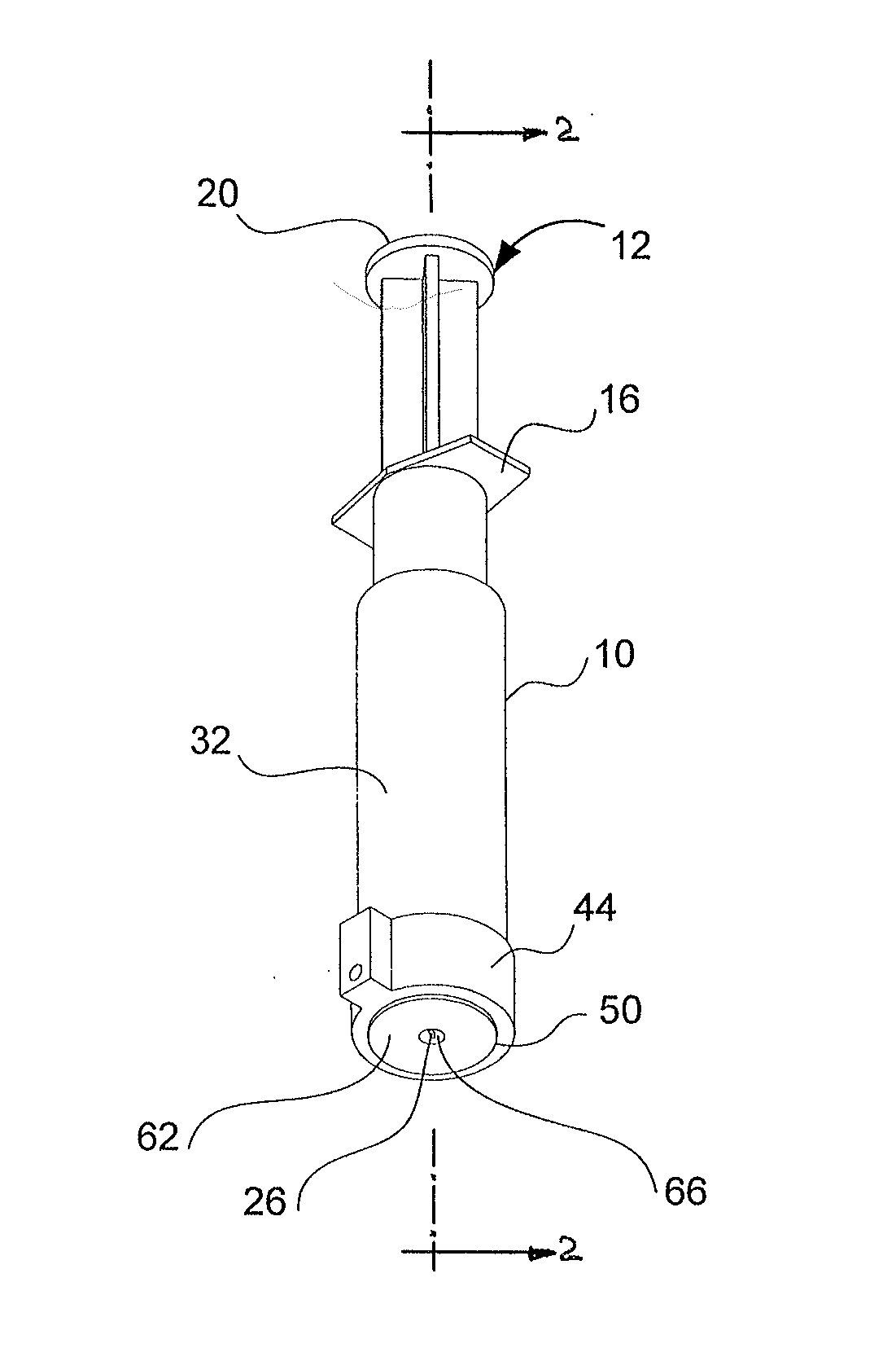
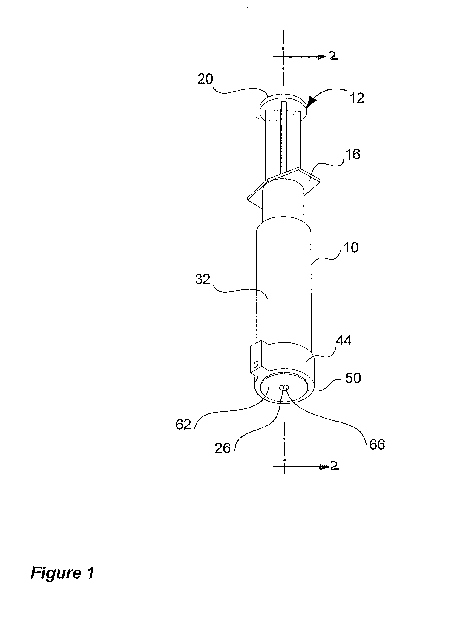
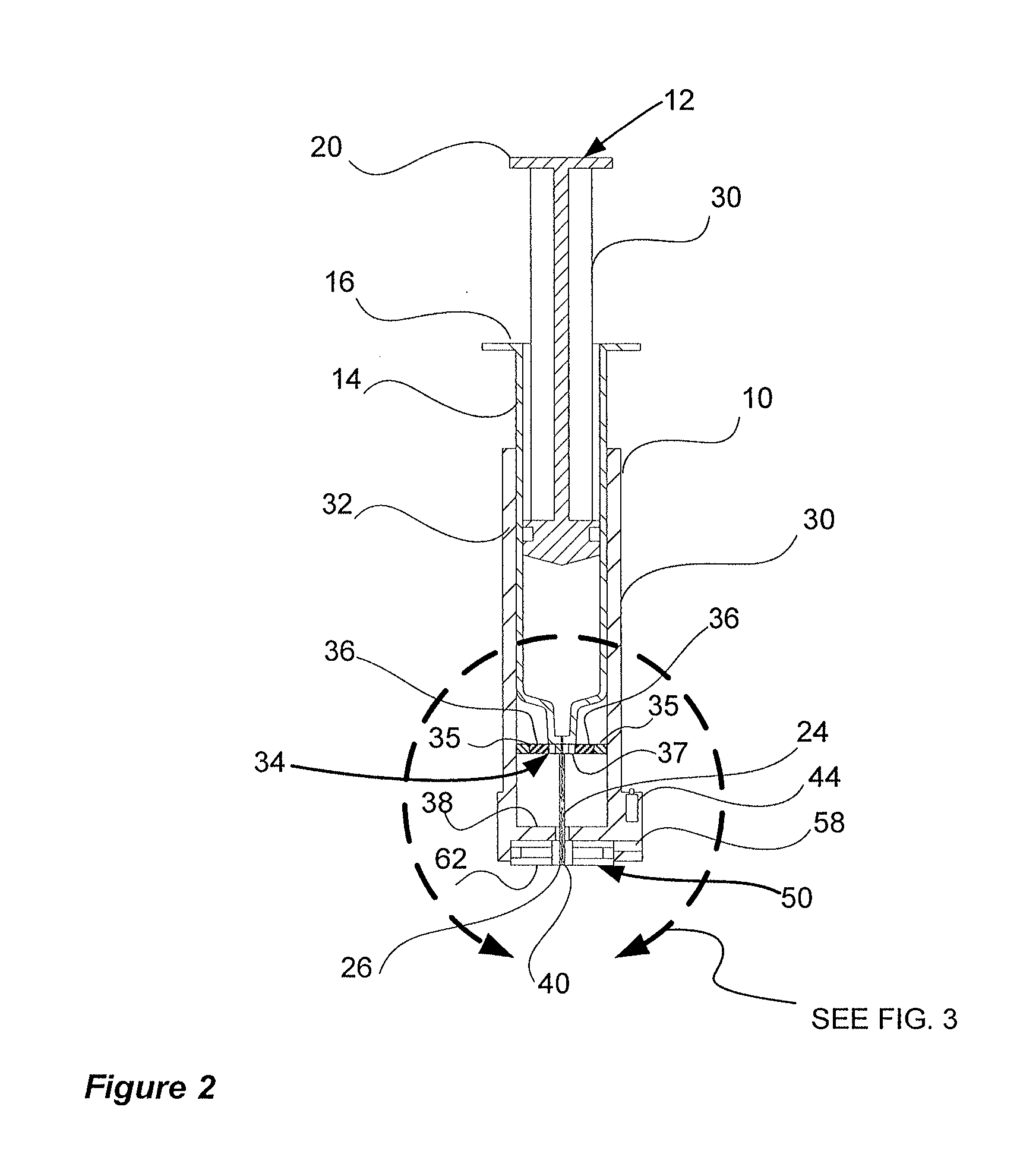
[0024]The invention disclosed herein is, of course, susceptible of embodiment in many different forms. Shown in the drawings and described herein below in detail are preferred embodiments of the invention. It is understood, however, that the present disclosure is an exemplification of the principles of the invention and does not limit the invention to the illustrated embodiments. For ease of description, skin cooling apparatus embodying the present invention is described herein below in a usual assembled position as shown in the accompanying drawings, and terms such as upper, lower, horizontal, longitudinal, proximal, distal, etc., may be used herein with reference to this usual position. However, the skin cooling apparatus may be manufactured, transported, sold or used in orientations other than that described and shown herein.

[0025]Referring now to FIGS. 1-3, skin cooling apparatus generally indicated at 10 is shown associated with a hypodermic syringe generally indicated at 12. H...


PUM


Abstract

Skin cooling apparatus is provided for use with a medical treatment device such as a hypodermic syringe or a skin ablation laser or other electromagnetic source. The skin cooling apparatus provides selective, localized cooling of the target area that is acted upon by the medical treatment device. Included is a support body engaging at least a portion of the medical treatment device, for supporting and orienting the medical treatment device to the target area. A solid state cooling device such as a thermoelectric or Peltier device is carried by the support body and includes a cooling surface facing the target area of a patient's skin surface. The support body may be flexible so as to allow the medical treatment device to be inclined relative to the skin surface. The support body may also include aiming structure for directing the medical treatment device to a particular point within the target area.

Description

CROSS-REFERENCE TO RELATED APPLICATIONS[0001]This application is a continuation-in-part of U.S. patent application Ser. No. 13 / 135,945, filed on Jul. 19, 2011, which, in turn, is a division of U.S. patent application Ser. No. 12 / 319,437, filed on Jan. 7, 2009, each of which is incorporated herein by reference.FIELD OF THE INVENTION[0002]The present invention pertains to the cooling of skin surface portions, to alleviate pain associated with medical treatment applied to the skin. The present invention also relates to apparatus and method to perform cooling of skin surface portions to which a medical treatment device is applied.BACKGROUND OF THE INVENTION[0003]Nerve endings in the skin layers are particularly sensitive to medical treatments that interact with the patient's skin. These types of medical treatments include, for example, hypodermic injections and skin ablation, especially using powerful laser ablation devices. No matter how necessary the medical treatment, the associated ...

Claims


Application Information

Patent Timeline
Patent Type & Authority Applications(United States)
IPC IPC(8): A61B18/20A61M5/42A61B18/22
CPCA61B18/203A61M5/422A61B18/22A61B5/150129A61B18/20A61B2018/00005A61B2018/00452A61B2018/00636A61M2205/3606A61B5/150022A61B5/150412A61B5/150503A61B5/15136A61B2018/207A61B2018/2244A61N5/0616
Inventor HALAKA, FOLIM G.
Owner HALAKA FOLIM G
Why Eureka
Try Eureka