On-demand power control system, on-demand power control system program, and computer-readable recording medium recording the same program
Inactive Publication Date: 2014-03-13
NITTO DENKO CORP
5 Cites 29 Cited by
AI-Extracted Technical Summary
Problems solved by technology
That is, the arbitration server updates the home appliance status table and power source status table at intervals of 2 to 3 seconds and cannot control power supply in real time in response to a request for power required by a user.
Additionally, since the volume of data processed at the time of calculating supplied power and capacity is enormous, ...
Method used
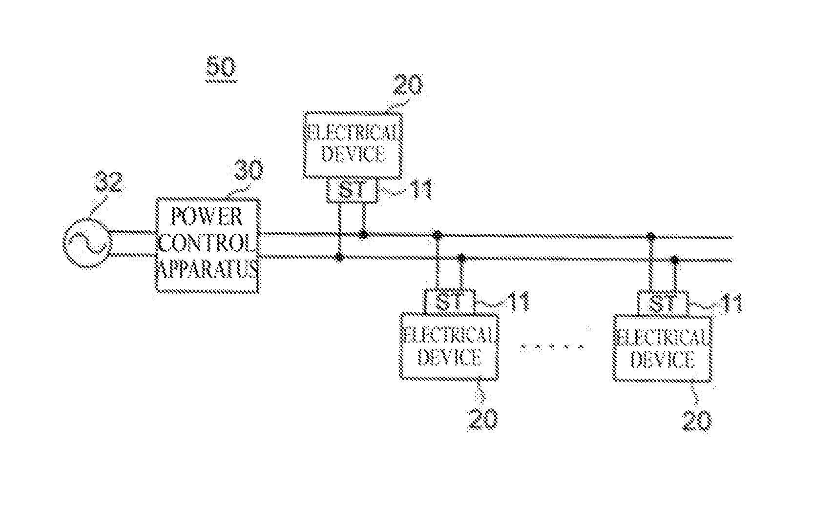
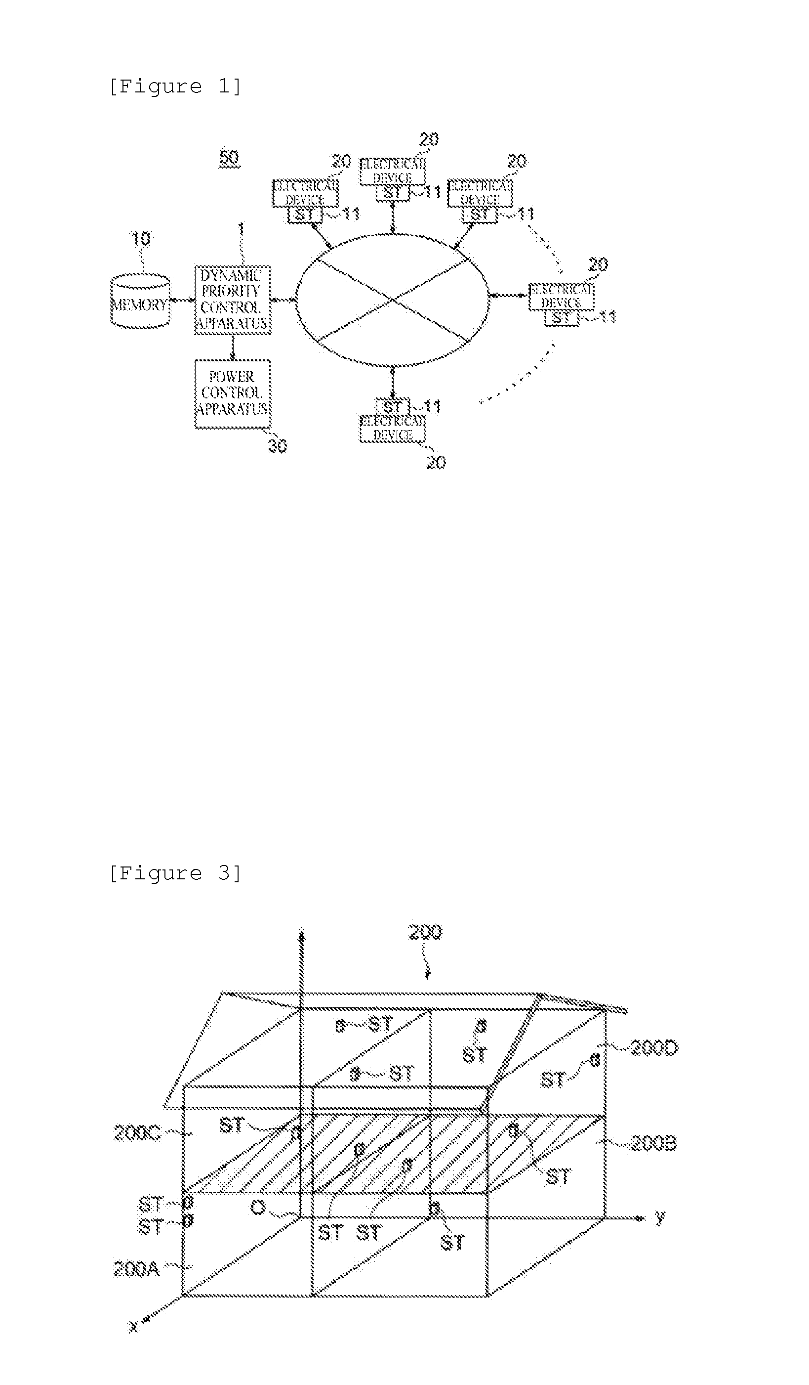
[0105]The EoD control system according to the present invention does not unconditionally supply power when a certain device is turned on, and power is requested. The EoD control system first transmits a message requesting power to the priority apparatus and determines, for each device, whether to enable power supply and suppliable power in the priority apparatus through adjustment of suppliable power, device priorities, and the like, on the basis of a user's pattern of power use. Since each device uses only allowed power, power consumption and consumed power do not exceed target values. The EoD control system is a system which can avoid power saving by a reduction in power consumption and a massive blackout during on-peak hours.
[0125]Upper limits for usable power include an upper limit (hereinafter referred to as a “ceiling”) for integral power consumption over a fixed period and an upper limit (hereinafter referred to as “maximum instantaneous power”) for instantaneous power. The maximum instantaneous power is given as an upper limit for an instantaneous value of power in each time period in order for a user to reduce contract demand or in order to respond to a request for on-peak reduction from an electric power company for maintaining the balance between supply and demand in a power network. The ceiling is given as an upper limit for integral power consumption over a fixed period (e.g., one day, one week, or one month) in order for a user to reduce electricity costs and CO2 emissions.
[0141]The initial target value T0(t) (W) that is the example of the power use plan is a plan for reducing a value at each time in a power use plan by a fixed percentage and setting initial target values such that the initial target values as a whole stay within upper limits (hereinafter referred to as a “fixed percentage reduction plan”). FIG. 9-1 shows the example. Examples for setting an initial target value are reducing only values during on-peak power use hours when used power is above instantaneous power of a power use plan for one day (hereinafter referred to as a “peak reduction plan” (FIG. 9-2) and reducing values according to power costs (hereinafter referred to as a “cost reduction plan” (FIG. 9-3). For example, if a reduction in power use during hours from 1 p.m. to 4 p.m. when most power is used is desired, power usage can be reduced by increasing the power costs for power usage during the time period. The reduction plans allows setting of initial target values, and initial target values can also be set using the reduction plans in combination. As described above, the priority apparatus can select a power use plan according to a reduction method required by a user.
[0170]With the procedure, a user can reduce power as much as he/she wants by setting the maximum suppliable power amount (a ceiling) by himself/herself.
[0177]The dynamic priority control means 1 composed of the initial targ...
Benefits of technology
[0060]An EoD control system according to the present invention can change the priorities of electrical devices according to an electrical device required by a user through the user's daily life and the user's status of use of the electrical device and can thus use a required electrical apparatus when necessary.
[0061]Additionally, the EoD control system according to the present invention is a system which controls power supply on the basis of a user's pattern of power use and maximum instantaneous power and a ceiling set by the user and can thus guarantee the maximum instantaneous power and ceiling set by the user without impairing the Quality of Life of the user using electrical devices. The EoD control system is also a system which changes the priorities of electrical devices on the basis of the power consumed by the electrical devices when a user requests power and can control power supply in real time.
[0062]Moreover, th...
Abstract
A dynamic priority control apparatus of the present invention is characterized by including means that calculate a difference between instantaneous power of an initial target value and actual instantaneous power, initial target value updating means that take into account the difference, calculating priorities of electrical devices means based on electrical device property class data, and power arbitration means that determines the electrical devices to be supplied power based on the total value of the consumed power and the priorities of the electrical devices.
Application Domain
Mechanical power/torque controlData processing applications +9
Technology Topic
Device PropertiesElectrical installation +6
Image
Examples
- Experimental program(2)
Example
First Embodiment
[0131]FIG. 8 is a functional block diagram of a first embodiment showing functions of a priority apparatus shown in FIG. 1.
[0132]Reference numeral 1 in FIG. 8 denotes a priority apparatus; 10, a memory; and 11, an ST. The priority apparatus is composed of initial target value updating means 120 and power arbitration means 122. Reference characters (1) denote consumed power transmitted from the ST. As preprocessing, the priority apparatus converts the consumed power to a power use plan which determines used power for a minimum control interval τ and stores the power use plan, instantaneous power of an initial target value, and maximum instantaneous power in a memory 10, before the priority apparatus is activated. Reference characters (2) denote a power request message transmitted from the ST. The power request message is transmitted to the power arbitration means 122.
[0133]The initial target value updating means 120 has a function of allocating a difference between instantaneous power with an initial target value and actual instantaneous power to subsequent instantaneous power with an initial target value to calculate an updated initial target value such that the updated initial target value does not exceed maximum instantaneous power. The power arbitration means 122 has a function of comparing, with the updated initial target value, a total value of power consumed by a device having transmitted the power request message and devices in operation and, if the total value is larger, selecting a device having a priority of the minimum value among the devices obtained on the basis of electrical device property class data (to be described later) and selecting a device according to device property.
(Preprocessing)
[0134]As prior processing to be performed before activating the priority apparatus, a process of setting the power use plan is performed. The power use plan setting process will be described below.
[0135]The priority apparatus stores consumed power calculated at intervals of 0.5 seconds which has been transmitted from the ST in the memory and stores instantaneous power that is obtained by adding up the consumed power to obtain a total value and averaging the total value in the memory at intervals of the minimum control interval τ (5 to 10 minutes). A past record of a user's actual use of power (e.g., instantaneous power and integral power consumption for one week, one month, or each of four seasons, spring, summer, autumn, and winter) is set as a power use plan and is stored in the memory in advance.
[0136]An EoD control system according to the present invention sets a value determined by a user (e.g., a value reduced by 30%) as a target value using a pattern of power use that is a past record of a user's actual use of power and makes a power use plan in advance. The EoD control system determines its ceiling and maximum instantaneous power and performs power control. The EoD control system according to the present invention performs actual control using the ceiling and maximum instantaneous power.
[0137]Accordingly, the priority apparatus according to the present invention sets in advance a power use plan using instantaneous power for each time period derived from a past record of a user's actual use of power and can set the power use plan in more detail.
[0138]Power used by each device is transmitted to the priority apparatus at all times, and the priority apparatus accumulates the used power in the memory.
[0139]An example of the power use plan will be described below. A power use plan is determined using instantaneous power in each minimum control interval τ (set to 10 minutes in a demonstration experiment (to be described later)). Let C (Wh) be a ceiling (an upper limit for integral power consumption) set by a user; M(t) (W), maximum instantaneous power (an upper limit for instantaneous power); and D(t) (W), a predicted value for power demand at time t. An initial target value T0(t) (W) is created from Equations (1) and (2).
D ′ ( t ) = { D ( t ) if D ( t ) ≦ M ( t ) M ( t ) otherwise ( 1 ) T 0 ( t ) = C ∑ t start t end τ D ′ ( t ) D ′ ( t ) ( 2 )
[0140]The priority apparatus controls each device according to the power use plan such that power of the initial target value T0(t) (W) falls below the maximum instantaneous power.
[0141]The initial target value T0(t) (W) that is the example of the power use plan is a plan for reducing a value at each time in a power use plan by a fixed percentage and setting initial target values such that the initial target values as a whole stay within upper limits (hereinafter referred to as a “fixed percentage reduction plan”). FIG. 9-1 shows the example. Examples for setting an initial target value are reducing only values during on-peak power use hours when used power is above instantaneous power of a power use plan for one day (hereinafter referred to as a “peak reduction plan” (FIG. 9-2) and reducing values according to power costs (hereinafter referred to as a “cost reduction plan” (FIG. 9-3). For example, if a reduction in power use during hours from 1 p.m. to 4 p.m. when most power is used is desired, power usage can be reduced by increasing the power costs for power usage during the time period. The reduction plans allows setting of initial target values, and initial target values can also be set using the reduction plans in combination. As described above, the priority apparatus can select a power use plan according to a reduction method required by a user.
[0142]As has been described above, as the prior processing to be performed before activating the priority apparatus, it is necessary to set a power use plan on the basis of a past record of a user's actual use of power and store in advance a ceiling and maximum instantaneous power as an initial target value which are obtained by reducing the power use plan using a reduction plan selected by the user in the memory. When the priority apparatus is activated, the initial target value updating means 120 (to be described later) performs a process (interval) of checking consumed power and updating an initial target value at fixed intervals (τ) using the initial target value as a target, and the power arbitration means 122 is composed of means for performing a process (event driven) of arbitrating between a device and different devices in response to a request from the device. The means will be described below. Note that power used by each device is transmitted to the priority apparatus at all times, and data on the used power is accumulated.
(1) Initial Target Value Updating Means
[0143]The initial target value updating means 120 for performing a process (interval) of updating an initial target value (for instantaneous power) at the minimum control intervals (τ) on the basis of the initial target value will be described.
[0144]When the priority apparatus is activated, control is performed using an initial target value for power per τ as a target at the time of actual power control. If a user acts differently from a past history, a reduction in power may be impossible in view of the QoL and the properties of devices in some cases. In such a case, actual instantaneous power temporarily exceeds an initial target value. In contrast, the number of devices to be used may be small, and actual instantaneous power may fall below an initial target value. Since devices are used by a person, actual instantaneous power depends on the person's behavior during use. If control is continued while initial target values are maintained in the cases, maintenance within upper limits cannot be finally achieved. FIG. 10 is a bar chart showing an example of actual instantaneous power when control is performed while initial target values are maintained.
[0145]A case is conceivable where power cannot be reduced to (or to below) an initial target value in view of a user's status of use of a device (e.g., since control is performed while initial target values are maintained, power of only a device such as a respirator which cannot be stopped exceeds an initial target value at a certain moment. In this case, instantaneous power may temporarily exceed an initial target value as long as the instantaneous power does not exceed maximum instantaneous power. Initial target values are updated such that an excess at this time is absorbed in a subsequent part of a power use plan. Although initial target values deviate from initially determined values, maintenance within a ceiling can be achieved by feeding back a difference between actual instantaneous power and an initial target value to subsequent initial target values while maintaining the QoL.
[0146]An allocation function is defined for giving feedback to an initial target value. The allocation function receives a difference between an initial target value and actual instantaneous power, allocates the difference to initial target values for times later than a time for the difference, and calculates instantaneous power of a new initial target value.
[0147]FIG. 11 is an explanatory chart of a case where control that feeds back a difference between actual instantaneous power and an initial target value to subsequent planned values is performed. When the priority apparatus is activated, and a control start time reaches a time tnow satisfying tnow−tstart=iτ, the priority apparatus updates a power use plan.
[0148]If i:=i+1, a power use plan Ti(t) represents a power use plan at time t after i updates, i.e., after a lapse of iτ. Reference character γ in Equation (3) denotes an allocation function for updating a power use plan, and the function allocates a difference between instantaneous power of an initial target value and actual instantaneous power to subsequent instantaneous power. Accordingly, differential power to be allocated to subsequent instantaneous power is determined by substituting the difference into Equation (3).
T i + 1 : = min ( γ ( T ^ i ( t now ) - E ^ ( t now ) , t now - t start ) T i ( t ) , M ) ( 3 ) E ^ ( t now ) = ∑ t start t now τ E total ( t ) ( 4 ) T ^ i ( t now ) = ∑ t start i τ T i ( t ) ( 5 )
[0149]Reference characters T1(tnow) in Equation (5) denote a current initial planned value, and reference characters E(tnow) denote current used power.
[0150]The chart shown in FIG. 11 is obtained using a method (hereinafter referred to as an “equal difference allocation method”) for equally dividing the difference and allocating a divided part to all of subsequent new initial target values. Another possible method is allocating the difference to only the one immediately succeeding instantaneous power (hereinafter referred to as an “instantaneous power allocation method”). As described above, difference allocation methods include the equal difference allocation method and instantaneous power allocation method. First, an overall power use plan is created. During actual control, an initial target value is updated so as not to exceed maximum instantaneous power to suit a status of use. This makes it possible to achieve maintenance within a ceiling while performing flexible control.
(3) Power Arbitration Means
[0151]The power arbitration means 122 for performing a process (event driven) of arbitrating between a device and different devices in response to a request from the device while maintaining the QoL, by prioritizing devices will be described.
[0152]A request for power from a device is issued at a time when a user wants to use the device, regardless of τ described above. Such requests include one issued by a device which can wait until the end of the minimum control interval τ of 5 to 10 minutes and one issued by a device which requires immediate supply of power. In the case of the latter device, control at the intervals τ causes a failure to supply power in time, which leads to a reduction in QoL. Power used by the power arbitration means upon receipt of a request for power is not instantaneous power but actual consumed power. With the use of actual consumed power, immediate decisions can be made in response to requests for power issued at various times, and whether to wait can be determined immediately.
[0153]The EoD control system requires a guide for determining to which one power is supplied when individual devices request power. Desired power cannot be supplied to all devices to achieve maintenance within upper limits, and which one of the devices requires power depends on the statuses of the devices and a user. Determination of to which device power is preferentially supplied matters. Accordingly, priority needs to be determined according to the property and status of a device. To this end, a priority function returning a value of 0 to 1 is set for devices, and power is preferentially supplied to one having a priority of a larger value. Note that QoL is enhanced when a device is supplied with power and is made available and that social contribution through a cost reduction and energy saving are not taken into account.
[0154]Since a power control method varies among devices, the properties of devices need to be known in advance in order to select a device for which supplied power is reduced in response to requests for power from the devices. A parameter representing the property of power requested by each device and a power control method for the device is denoted by QoEn. As for QoEn, devices are classified on the basis of the device power control methods below.
(1) Adjustable Device (based on whether power supplied during operation can be changed) (a set of devices as members is denoted by Aadj)
(2) Waitable Device (based on whether a device can wait to be supplied with power when the device is activated) (a set of devices as members is denoted by Await)
(3) Suspendable Device (based on whether power supply can be suspended during operation) (a set of devices as members is denoted by Asus)
[0155]By combining the three types of power control methods, devices are classified into eight classes, as shown in Table 2. Respective pieces of data for eight classes are defined as “electrical device property class data” and are used. The priorities of devices are controlled using the electrical device property class data.
[0156]The eight classes are tied to device names identified by IDs in the “Home Appliance” column, and a device to which priority is to be given is determined using the priorities of devices in use. For example, when the priority apparatus receives a power request message from the ST, the priority apparatus determines whether to permit or refuse the request, using the priorities of a device having transmitted the message and devices in operation and the electrical device property class data.
[0157](1) Devices classified as adjustable devices include one whose function can be used even if supplied power is slightly reduced during use. Examples of such devices include a dryer and a light bulb. (2) Some devices may not cause any functional problems even without immediate power supply in response to requests for power from the devices as long as power is supplied by a predetermined time. Examples of such devices include a rice cooker and a washing machine. (3) Some devices have little effect on the life of a user using the devices even if power supply is suspended during use. Examples of such devices include an air conditioner and a refrigerator.
[0158]Note that, for example, a respirator is classified into class 8 in order to ensure safe and comfortable living. Although devices are classified into the eight classes, classes to which the devices belong are not fixed and are not limited to the classes shown in Table 2. A user can arbitrarily determine into which class each device is to be classified. For example, if a bedridden elderly person selects an air conditioner as an always necessary device, the air conditioner is classified into class 8. In other words, devices including a gas detector, a respirator, and a network device (e.g., a router) as electrical devices which cannot be classified on the basis of the adjustable, suspendable, and waitable power control methods fall into class 8.
TABLE 2 Home appliance Class Adjustable Waitable Suspendable (Electrical device ID) 1 YES YES YES notebook PC and boiler 2 YES YES NO toilet seat with warm- water shower feature and microwave oven 3 YES NO YES heater, air conditioner, and refrigerator 4 YES NO NO TV and dryer 5 NO YES YES dishwasher and washing machine 6 NO YES NO rice cooker and toaster 7 NO NO YES copier and electric pot 8 NO NO NO gas detector, respirator, and network device (e.g., router)
1. Adjustable Device
[0159]A power-adjustable example is a dryer. As shown in FIG. 12, the level of user satisfaction is highest when power as requested is supplied to a power-adjustable device and does not change much even if supplied power is slightly reduced. However, if the power is significantly reduced, the capability of the home appliance is restricted, and the level of user satisfaction decreases. When the power is finally reduced to below a certain level, the home appliance cannot fulfill its function. That is, priority can be given using a monotonically decreasing function with respect to supplied power, which makes the priority of supply of the minimum power required for use high and makes the priority of supply of power as requested low. Letting preqa be power requested by a home appliance a; and pmina be the minimum required power, the power arbitration means defines a priority Priaadj(p) of the power-adjustable home appliance as follows:
Pri a adj ( p ) = { 0 if p a req ≤ p 1 - ( p a req - p p a req - p a min ) α a adj if p a min p p a req 1 if p ≤ p a min ( 6 )
An example of the priority (adjust) of a power-adjustable device thus designed is as in FIG. 12 and Equation (6).
2. Waitable Device
[0160]An example waitable at startup is a rice cooker. The rice cooker is a home appliance which only needs to complete operation by a certain time and whose startup time can be delayed. That is, as shown in FIG. 13, priority may be defined so as to be low immediately after power is requested and increase as a time when the home appliance needs to be started up gets closer.
[0161]Letting treqa be a requested time; and tmusta be a time when a waitable home appliance a needs to be started up, a priority Prishifta(t) of the waitable home appliance a is defined as follows:
Pri a shift ( t ) = { 1 - ( t - t a req t a must - t a req ) α a shift if t ≤ t a must , 1 if t t a must ( 7 )
3. Suspendable Device
[0162]A suspendable example is an air conditioner. A suspendable device is a home appliance which acts toward a certain steady state during operation and, once the steady state is reached, can maintain the steady state even after operation is suspended, like temperature setting of an air conditioner. Assume a case of such a home appliance. As shown in FIG. 14, immediately after operation is started, the home appliance acts toward a steady state, and a high priority needs to be given. When the steady state is reached, since the steady state is maintained even if operation is suspended, the priority can be reduced. During the suspension, since the home appliance deviates from the steady state as time passes, the home appliance needs to resume operation with the increased priority. A priority Priinta(t) of the suspendable home appliance is defined separately for a case where a is in operation and a case where a is in abeyance as follows:
Pri a int ( t ) = { Pri a run ( t ) if a is in operation Pri a sus ( t ) if a is in abeyance ( 8 ) Pri a run ( t ) = { ( t - t a enable t a stop - t a enable ) α a run if t ≤ t a enable 1 otherwise ( 9 ) Pri a sus ( t ) = { 1 - ( t - t a sus t a must - t a sus ) α a sus if t ≤ t a must 1 otherwise ( 10 )
4. Priority of General Home Appliance
[0163]Generally, classes of home appliances are defined using a combination of the three properties shown in Table 2. By combining the priorities defined for the properties, the priority functions for the classes are defined as shown under the item of priority function in Table 3. For example, the priority function of class 1 is defined by the product of the priority functions corresponding to the respective properties as follows:
Pria(t,p)=Priaadj(p)Priashift(t)Priaint(t) (11)
[0164]The priority function of class 8 is 1, which means that power is always preferentially supplied.
TABLE 3 Class Priority function Pria(p, t) 1 Priαadj(p) · Priαshift(t) · Priαint(t) 2 Priαadj(p) · Priαshift(t) 3 Priαadj(p) · Priαint(t) 4 Priαadj(p) 5 Priαshift(t) · Priαint(t) 6 Priαshift(t) 7 Priαint(t) 8 1
[0165]FIG. 15 is a sequence chart for explaining a procedure by which the priority apparatus supplies power according to priority in response to a power request message.
[0166]1. The ST connected to a device transmits a power request message to the priority apparatus (1).
[0167]2. The priority control apparatus 1 determines the priorities of the device having transmitted the power request message and a device in operation from a current suppliable amount and a home life pattern.
[0168]3. The priority control apparatus 1 transmits, in response, a power assignment message (2) including consumed power and time permitted to the device or a refusal message (2′) for a device not permitted to be supplied with power according to the priority of the device. If the priority of the device in operation is low, and the device is desired to be stopped or power to the device is desired to be reduced, the priority control apparatus 1 transmits an interrupt message (3) to the device.
[0169]4. A device permitted to use power operates with permitted power for a permitted time period. A device for which power use is refused transmits a reassignment message after a fixed period of time (4).
[0170]With the procedure, a user can reduce power as much as he/she wants by setting the maximum suppliable power amount (a ceiling) by himself/herself.
[0171]The procedure will be described in detail. A device areq requiring power transmits a power request message (Table 3) to a server (1 in FIG. 15). The server having received the request compares a sum E′total (tnow) of total used power Etotal (tnow) at a current time tnow and requested power Ereq with a power use plan Ti(tnow) immediately. If the overall power (the sum) E′total (tnow) is below the plan, the server permits the power Ereq as requested (Equation (12)). If areqεAwait, the server refuses the request (2′ in FIG. 15). Otherwise, the server calculates the priorities of devices. The server reduces the power for a different device lower in priority than the device areq as interrupt processing (3 in FIG. 15) (Equation 13), secures power to update the total used power Etotal (tnow), and decides to reduce supplied power according to the property of the device (Equation 14). The server transmits a message with information in Table 5 (e.g., suppliable power Esupply) to the device areq immediately, and the device uses power according to the message. A policy about power use is determined again for the device and the device areq, for which power supply is refused/interrupted, in a next interval process (4 in FIG. 15).
E supply = { E req if E total ′ ( t now ) ≤ T i ( t now ) E refuse otherwise ( 12 ) E refuse = { 0 if a ∈ A wait E adj else if a ∈ A adj E req otherwise ( 13 ) E adj = max ( T i ( t now ) - E total ( t now ) , E req min ) ( E req min : minimum startup power for requesting device ) ( 14 )
[0172]As described above, the priority apparatus having received a request from each device compares the sum E′total (tnow) of the total used power Etotal (tnow) in operation at the current time tnow and the requested power Ereq with the power use plan Ti(tnow). If the sum E′total (tnow) is above the power use plan Ti(tnow), the priority apparatus reduces the power for a device amin with a minimum priority according to Equation 13 and gives a priority update.
[0173]Data of a power request message which the ST transmits to the priority apparatus will be described with reference to Table 4.
[0174]Pieces of data in the Value column and the Class in need column are tied to each of the items, device ID, requested power, minimum startup power, suspendable time period, and required startup time in the Item column. The ST transmits pieces of data as sets of a value and a class in need to the priority apparatus.
TABLE 4 Item Value Class in need Electrical device ID ID 1-8 Requested power Ereg(W) 1-8 Minimum startup Emin(W) 1-4 power Suspendable time Time 1, 3, 5, 7 period Required startup time Time 1, 2, 5, 6
[0175]Data of a message which the priority apparatus transmits to the ST in response will be described with reference to Table 5.
[0176]A piece of data in the Value column is tied to each of the items, device ID, message type, permitted instantaneous power, and permitted use time period in the Item column. The priority apparatus transmits the pieces of data to the ST.
TABLE 5 Item Value Device ID ID Message type permission/refusal Permitted average power Esupply(W) Permitted use time period Time
[0177]The dynamic priority control means 1 composed of the initial target value updating means 120 and power arbitration means 122 described above can avoid power saving by a reduction in integral power consumption and a massive blackout during on-peak hours without causing a situation in which instantaneous power exceeds its upper limit or integral power consumption exceeds its upper limit C (Wh).
Example
Second Embodiment
[0178]The above-described dynamic priority control apparatus 1 can finally control instantaneous power to (or to below) maximum instantaneous power and perform control so as to maintain integral power consumption within the upper limit C (Wh). However, an unexpected increase in instantaneous power may occur due to, e.g., a load change during use of a device, and instantaneous power may exceed the maximum instantaneous power. A second embodiment for coping with such a case will be described.
[0179]FIG. 16 is a functional block diagram of the second embodiment.
[0180]A priority apparatus is composed of initial target value updating means 120, power arbitration means 122, and continuous monitoring means 124.
[0181]The initial target value updating means 120 and power arbitration means 122 have the same functions as the means described above, and a description thereof will be omitted.
[0182]The continuous monitoring means 124 monitors consumed power at all times. If the overall consumed power exceeds maximum instantaneous power for a certain time period d (about 0.5 to 2 seconds) or longer, the power arbitration means 122 performs arbitration based on priority such that the overall consumed power falls below the maximum instantaneous power, i.e., the overall consumed power falls below maximum instantaneous power M instead of the overall consumed power without waiting for a lapse of τ.
[0183]The former priority apparatus maintains the QoL by immediately making a decision about a request for power transmitted from a device when, for example, the device is turned on and not interfering with use of the device. The latter priority apparatus updates a planned value and performs arbitration between devices in response to a request for continuation from each device. If supplied power is continuously changed on a moment-to-moment basis, an unstable situation (e.g., the brightness of a light bulb changes at all times, and the light bulb flickers) may occur. Overall stabilization is ensured by introduction of the minimum control interval τ. Maintenance within maximum instantaneous power is guaranteed by monitoring instantaneous power at all times for an excess over the maximum instantaneous power.
[0184]FIG. 17 is a general flow chart showing preprocessing of a CPU 1a before the priority apparatus is activated.
[0185]Before the CPU 1a of the priority apparatus is activated, a process of setting initial target values of a power use plan and storing the initial target values in a memory is performed as the preprocessing in step S1.
[0186]FIG. 18 is a flow chart showing overall processing of the CPU 1a after the CPU 1a of the priority apparatus is activated. After the CPU 1a of the priority apparatus is activated, the CPU 1a performs an initial target value updating process in step S3 and a priority arbitration process in step S5.
[0187]FIG. 19 is a flow chart of the power use plan setting process in step S1 described above.
[0188]As shown in FIG. 19, the CPU 1a converts consumed power for, e.g., one day, one week, or one month transmitted from an ST of each device to instantaneous power which is obtained by adding up consumed power for each of intervals of the minimum control interval τ (e.g., 10 minutes) to obtain a total value and averaging the total value and integral power consumption in step S11. Letting C (Wh) be a ceiling (an upper limit for instantaneous power) set by a user from the instantaneous power and integral power consumption; M(t) (W), maximum instantaneous power (an upper limit for instantaneous power); and D(t) (W), a predicted value for power demand at time t, an initial target value T0(t) (W) which is an example of a power use plan is created from Equations (1) and (2) in step S13.
D ′ ( t ) = { D ( t ) if D ( t ) ≦ M ( t ) M ( t ) otherwise ( 1 ) T 0 ( t ) = C ∑ t start t end τ D ′ ( t ) D ′ ( t ) ( 2 )
[0189]As the preprocessing before activation, the initial target value T0(t) (W) is stored in the memory in advance.
[0190]Other power use plans include a peak reduction plan (FIG. 9-2) in which values are reduced only during on-peak power use hours when power usage is above instantaneous power of a power use plan for one day and a cost reduction plan (FIG. 9-3) in which values are reduced according to power costs. The reduction plans allow setting of initial target values, and initial target values can also be set using the reduction plans in combination.
[0191]FIG. 20 is a flow chart of the initial target value updating process in step S3 described above.
[0192]As shown in FIG. 20, the CPU 1a calculates allocated power from a difference between instantaneous power of an initial target value and actual instantaneous power by a difference allocation method (an equal difference allocation method or an instantaneous power allocation method), adds the allocated power to subsequent instantaneous power with the initial target value, and calculates an updated initial target value in step S31. The CPU 1a compares maximum instantaneous power with the updated initial target value in step S33. If Yes in S35, the CPU 1a updates the subsequent instantaneous power with the initial target value to have the updated initial target value in step S37. If No in S35, the CPU 1a updates the initial target value to be the maximum instantaneous power and sets the maximum instantaneous power as the updated initial target value in step S39.
[0193]FIGS. 21-1 to 21-4 are flow charts of the priority arbitration process in step S5 described above.
[0194]As shown in FIG. 21-1, when the CPU 1a receives a power request message from an ST in step S51, the CPU 1a calls up the consumed power of a device having transmitted the power request message and devices in operation for a time when the power request message is received from the memory in step S53, adds up the consumed power of the devices, and obtains a total value. In step S55, the CPU 1a refers to Table 3, calculates the priorities of the devices on the basis of priority functions, and stores values of the priorities in the memory. The CPU 1a compares the total value with an updated initial target value transmitted from the initial target value updating means in step S57. If Yes in step S59, the CPU 1a transmits a permission message to the ST of the device having performed transmission in step S61 and ends the process. If No in step S59, the CPU 1a calls up the priorities from the memory and selects a device with the minimum priority in step S63 and advances to step S65. As shown in FIG. 21-2, the CPU 1a refers to Table 2 and determines whether the device is adjustable in step S65. If Yes in step S67, the CPU 1a transmits an interrupt message for reducing power to the device in step S69, updates the total value of the consumed power on the basis of the reduced power in step S71, and returns to step S59. If No in step S67, the CPU 1a advances to step S73.
[0195]As shown in FIG. 21-3, the CPU 1a determines whether the device corresponds to the ST having transmitted the request message and is waitable in step S73. If Yes in step S75, the CPU 1a transmits a refusal message to the ST of the device in step S77, updates the total value of the consumed power by subtracting the consumed power of the device from the total value in step S79, and returns to step S59. If No in step S75, the CPU 1a advances to step S81. As shown in FIG. 21-4, the CPU 1a determines whether the device does not correspond to the ST having transmitted the request message and is suspendable in step S81. If Yes in step S83, the CPU 1a transmits a refusal message to the ST of the device in step S85, updates the total value of the consumed power by subtracting the consumed power of the device from the total value in step S87, and returns to step S59. If No in step S83, the CPU 1a ends the process.
[0196]FIGS. 22-1 to 22-3 are flow charts of the continuous monitoring process in step S7 described above.
[0197]As shown in FIG. 22-1, the CPU 1a calls up maximum instantaneous power from the memory in step S91. The CPU 1a calls up the consumed power of devices in operation from the memory, adds up the consumed power of the devices, and obtains a total value at intervals δ (0.5 to 2 seconds) in step S93. The CPU 1a refers to Table 2, calculates the priorities of the devices on the basis of priority functions, and stores the priorities in the memory in step S95. The CPU 1a compares the maximum instantaneous power with the total value of the consumed power in step S97. If the CPU 1a determines that the total value of the consumed power is smaller in step S99, the CPU 1a ends the process. On the other hand, if the CPU 1a determines that the total value of the consumed power is larger in step S99, the CPU 1a calls up the priorities from the memory and selects a device with the minimum priority in step S101, and advances to (4).
[0198]As shown in FIG. 22-2, the CPU 1a refers to priority class data in Table 2 and determines whether the device is adjustable in step S103. If Yes in step S105, the CPU 1a transmits an interrupt message for reducing power to the device in step 107. The CPU 1a updates the total value of the consumed power on the basis of the reduced power in step S109 and returns to step S99. The loop is executed repeatedly until the total value of the consumed power becomes smaller than the maximum instantaneous power. If No in step S105, the CPU 1a advances to (5).
[0199]As shown in FIG. 22-3, the CPU 1a determines whether the device is suspendable in step S111. If Yes in step S113, the CPU 1a transmits a refusal message to an ST of the device in step S115, updates the total value of the consumed power by subtracting the consumed power of the device from the total value in step S117, and returns to step S113. The loop is repeatedly executed until the total value of the consumed power becomes smaller than the maximum instantaneous power.
[0200]As can be seen from the configuration in which the loop is repeatedly executed until the total value of the consumed power becomes smaller than the maximum instantaneous power, the priority apparatus controls supply of power to electrical devices such that the power is always below maximum instantaneous power.
[0201]As can be seen from the procedure in step S51 to step S87 of the power arbitration means and the device property class data, the priority apparatus is targeted at all devices installed in households and offices. Even if devices with three types of properties are not all installed (e.g., an adjustable device is not installed), a ceiling and an upper limit for maximum instantaneous power are not exceeded.
[0202]As described above, the used power of devices is transmitted to the priority apparatus at all times, and the priority apparatus accumulates the used power in the memory. Integral power consumption over a fixed period (e.g., one day, one week, or one month) is obtained by cumulating the accumulated used power of the devices. Since the power arbitration means controls power supply to the electrical devices such that a the initial target value T0(t) (W) in Equation (2) above is met, an upper limit (ceiling) for the integral power consumption is not exceeded.
[0203]For ease of comprehension of the priority arbitration process illustrated by the priority arbitration process flow chart in FIG. 21, the process will be described in the context of an example.
[0204]FIG. 23 are explanatory views for explaining processing by the power arbitration means.
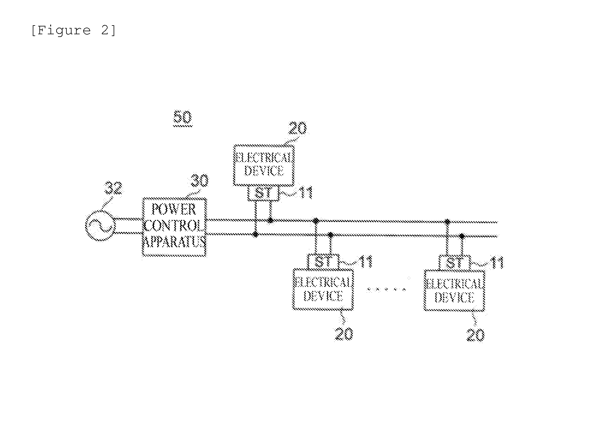
[0205]First, a priority arbitration process according to the example will be described using six types of devices, a TV (1), an air conditioner (2), a pot (4), a living room light (11), a bedroom light (12), and a corridor light (15), among devices installed in a model house shown in FIG. 5. Accordingly, the example is an example using only the light (15) installed in a corridor, the TV (1) installed in a living room, the air conditioner (2), the pot (4), the living room light (11), and the light (12) installed in a bedroom. The numerals represent the positions of switches at which the devices are installed or arranged.
(Example of Power Arbitration Means)
[0206]In the example, an initial target value for power is set to 800 W, maximum instantaneous power is set to 2 kW, only the pot is OFF, and the pot requires power of 1.2 kW. The example is an example showing how the priorities of the devices change and processing to be performed by the power arbitration means to secure power of 1.2 kW for the port during the change, when the 1.2 kW pot is turned on under the set conditions.
[0207]FIG. 23-1 is a view showing the power status of each device before the pot is turned on. The term “No.” displayed on the right side of FIG. 23-1 indicates the priority rank of each device, and a smaller value represents a higher priority. Only the pot is off, the other devices are operating, and the total of the power of the devices is 771 W.
[0208]FIG. 23-2 shows a situation in which the pot has been turned on and is requesting power of 1.2 kW. The requested power of 1.2 kW, however, is above the initial target value of 800 W and almost causes excess (1.974 kW) over the maximum instantaneous power of 2 kW. For this reason, the request for power is not permitted, and the pot is kept waiting until the pot reaches first place in the priority ranking. FIG. 23-3 shows that the pot has moved up gradually to reach first place in the priority ranking. Referring to FIG. 23-4, since the pot has reached first place in the priority ranking, the pot (1200 W) is turned on after the light (No. 6) in a corridor with a minimum priority is turned off. It can be seen that although the total power of the devices is above the initial target value of 800 W, the total power is 1928 W and is not above the maximum instantaneous power of 2 kW.
[0209]As can be seen from the example of the pot whose consumed power is 1.2 kW, activating the 1.2 kW pot requesting power without stopping the TV and air conditioner can be implemented without impairing the QoL of an ordinary person. This is because the power arbitration means instantaneously calculates the priorities of devices and a device to be preferentially selected is determined on the basis of the priorities and the properties of the devices.
(Effectiveness of EoD Control System)
[0210]It will be demonstrated that an EoD control system according to the present invention can implement considerable power saving without impairing the QoL through actual life.
[0211]Three subjects A, B, and C were subjected to a QoL demonstration experiment in the same smart apartment.
[0212]The living experiment used the smart home appliances and conventional home appliances below.
[0213]Smart Home Appliances (Network-Based Power Control)
[0214]Lights (in a living room and a bedroom), a television, an air conditioner, a microwave oven, a washing machine, a humidifier, a heater, and a rice cooker
[0215]Conventional Home Appliances (Power Control Based on Smart Tap)
[0216]Lights (in a hallway, a kitchen, a washroom, a toilet, and a bathroom), an electromagnetic cooker (IH), a refrigerator, an electric pot, and a toilet seat with a warm-water shower feature
(Experiment Description)
[0217]Each subject spent a daily life without power saving and learned a standard pattern of consumed power.
[0218]The subject spent a life in which integral power consumption for one day was 10% lower than the standard pattern and a life in which integral power consumption for one day was 30% lower.
[0219]Obtained data were numerically analyzed, and effects of the lives with reduced power on QoL were evaluated.
[0220]FIG. 24-1 is a chart showing a pattern of consumed power at the time of normal use and respective patterns of instantaneous power in a power use plan and an experimental plan with a 10% reduction by a priority apparatus.
[0221]FIG. 24-2 is a chart showing a pattern of consumed power at the time of normal use and respective patterns of instantaneous power in a power use plan and an experimental plan with a 30% reduction by the priority apparatus.
[0222]FIGS. 24-1 and 24-2 show that the conventional pattern of consumed power and the patterns of instantaneous power in the cases of a 10% reduction and a 30% reduction are similar and that an upper limit in the conventional pattern of consumed power is not exceeded.
[0223]FIG. 25-1 is a chart showing integral power consumption at the time of normal use and integral power consumption in the power use plan and the experimental plan with a 10% reduction by the priority apparatus.
[0224]FIG. 25-2 is a chart showing the integral power consumption at the time of normal use and integral power consumption in the power use plan and the experimental plan with a 30% reduction by the priority apparatus.
[0225]In both of the 10% and 30% reduction cases, integral power consumption at the time of normal use, integral power consumption based on an initial target value, and integral power consumption based on actually used power are mostly ranked in that order from highest to lowest. FIGS. 25-1 and 25-2 show that an upper limit for conventional integral power consumption is not exceeded.
[0226]Values in FIGS. 24 and 25 show that consumed power and integral power consumption are reduced even without changing the pattern of a daily life.
[0227]We listened to the actual life experience of the three subjects and checked whether there was any problem in the smart apartment where the EoD control system was installed.
(Actual Life Experience of Three Subjects)
[0228]Subjects A, B, and C
[0229]Overall, they could live without any particular inconvenience, regardless of rate of power reduction.
[0230]Subject A
[0231]He/she was conscious of a power reduction life only when the lighting was poor or the picture on the TV screen was not bright enough and cared no longer about the power reduction life when he/she got used to it.
[0232]Subject B
[0233]He/she was conscious only when the electric pot was slower in boiling water and cared no longer about the power reduction life when he/she got used to it.
[0234]Subject C
[0235]He/she reduced power for home appliances other than those for cooking at the peak of cooking.
[0236]It was found from the actual life experience of the three subjects that a person could live without any particular inconvenience, regardless of rate of power reduction (10% or 30%).
[0237]FIG. 26-1 is a chart showing the instantaneous power of six types of devices in the experimental plan with a 10% reduction by the priority apparatus.
[0238]FIG. 26-2 is a chart showing the instantaneous power of the six types of devices in the experimental plan with a 30% reduction by the priority apparatus.
[0239]The six types of devices are a TV, an electric pot, an electromagnetic cooker (IH stove), a refrigerator, a washing machine, and a light.
[0240]FIG. 26 are charts showing graphs of instantaneous power for the six types of electrical devices in respective power use plans with 10% and 30% reductions.
[0241]In the 10% reduction case in FIG. 26-1, the consumed power of the electric pot and washing machine peak at 1:30 and 11:00, respectively. In contrast, in the 30% reduction case in FIG. 26-2, the consumed power of the electric pot and washing machine peak at 22:00 and 9:40, respectively. It can be seen that the peak time for the electric pot is about three hours and a half earlier, and the peak time for the washing machine is about an hour and forty minutes earlier.
CONCLUSION
[0242]An EoD control system according to the present invention is a system for supplying power on the basis of arbitration through exchange of messages between a device and a priority apparatus. When a user turns on a device, power is supplied after a lapse of 2 to 3 seconds, to which a refresh timer counts, in the supply/demand arbitration system in Patent Literature 2. In contrast, according to the present invention, power is instantaneously supplied after the steps 1) to 4) below. 1) A device transmits a “power request message” with requested power and a priority to a priority apparatus. 2) The priority apparatus performs arbitration to determine whether to supply power to the device and supplied power on the basis of the priority of the device at the time. 3) The priority apparatus transmits a “power assignment (permission/reduction/refusal) message” to the device according to a result of the arbitration. 4) The device having received the “power assignment message” operates according to the message.
[0243]The EoD control system is targeted only at commercial power sources, and power can be generally used as much as a user likes within contract demand. The EoD control system provides, as parameters which can be set by a user himself/herself, two upper limits, an upper limit for instantaneous power (maximum instantaneous power) and an upper limit for integral power consumption (a ceiling). By giving the maximum instantaneous power as an upper limit for used power for each time period, it is possible to respond to a request for a reduction in contract demand from a user or a request for on-peak reduction from an electric power company for maintaining the balance between supply and demand in a power network. The ceiling given as an upper limit for integral power consumption over a fixed period (e.g., one day, one week, or one month) allows a user to reduce electricity costs and CO2 emissions.
[0244]The EoD control system adopts 1) dynamic device priority for determining to which device power is supplied and for which device power is reduced in order to reduce power while maintaining the Quality of Life, 2) power use plan setting means for processing instantaneous power in order to achieve a ceiling and an upper limit for maximum instantaneous power on the basis of a life pattern of an ordinary person, 3) power arbitration means for processing consumed power in order to supply power in real time in response to a request for power from a device, and 4) continuous monitoring means for processing instantaneous power in order to prevent instantaneous power from increasing unexpectedly due to, e.g., a load change and exceeding maximum instantaneous power. It can be seen that this adoption allows the EoD control system to solve all of the conventional problems.
PUM


Description & Claims & Application Information
We can also present the details of the Description, Claims and Application information to help users get a comprehensive understanding of the technical details of the patent, such as background art, summary of invention, brief description of drawings, description of embodiments, and other original content. On the other hand, users can also determine the specific scope of protection of the technology through the list of claims; as well as understand the changes in the life cycle of the technology with the presentation of the patent timeline. Login to view more.