
Gas substitution control system and method for bi-fuel engine

a control system and bi-fuel technology, applied in the direction of electrical control, process and machine control, instruments, etc., can solve the problems of expensive retrofitting and rare torque sensors in the original engine equipment, and achieve the effect of fast indication of diesel fuel flow variations

Inactive Publication Date: 2014-03-13
CONTINENTAL CONTROLS CORP
View PDF37 Cites 20 Cited by
  • Summary
  • Abstract
  • Description
  • Claims
  • Application Information

AI Technical Summary

Benefits of technology

The patent describes two embodiments of a control system for gas suspension systems in engines. The first embodiment introduces a gas flow bias to reduce gas flow rate during acceleration to prevent engine misfire. The second embodiment utilizes a fast-response diesel flow meter to measure the difference between supply and return flows, which is then averaged to provide a quick indication of changes in diesel fuel flow. These advancements provide faster and more accurate control over the gas suspension system, improving performance and efficiency of the engine.

Problems solved by technology

However, pumps, compressors, vehicle drives, and the like have no such unambiguous load-indicating parameters; their loads must be inferred from equipment data that is typically complex and unique to their particular model and situation.
Of course, output shaft torque is a valid load parameter, but torque sensors are rarely part of original engine equipment and are costly to retrofit.

Method used


Image

  • Gas substitution control system and method for bi-fuel engine
  • Gas substitution control system and method for bi-fuel engine
  • Gas substitution control system and method for bi-fuel engine

Examples


Embodiment Construction

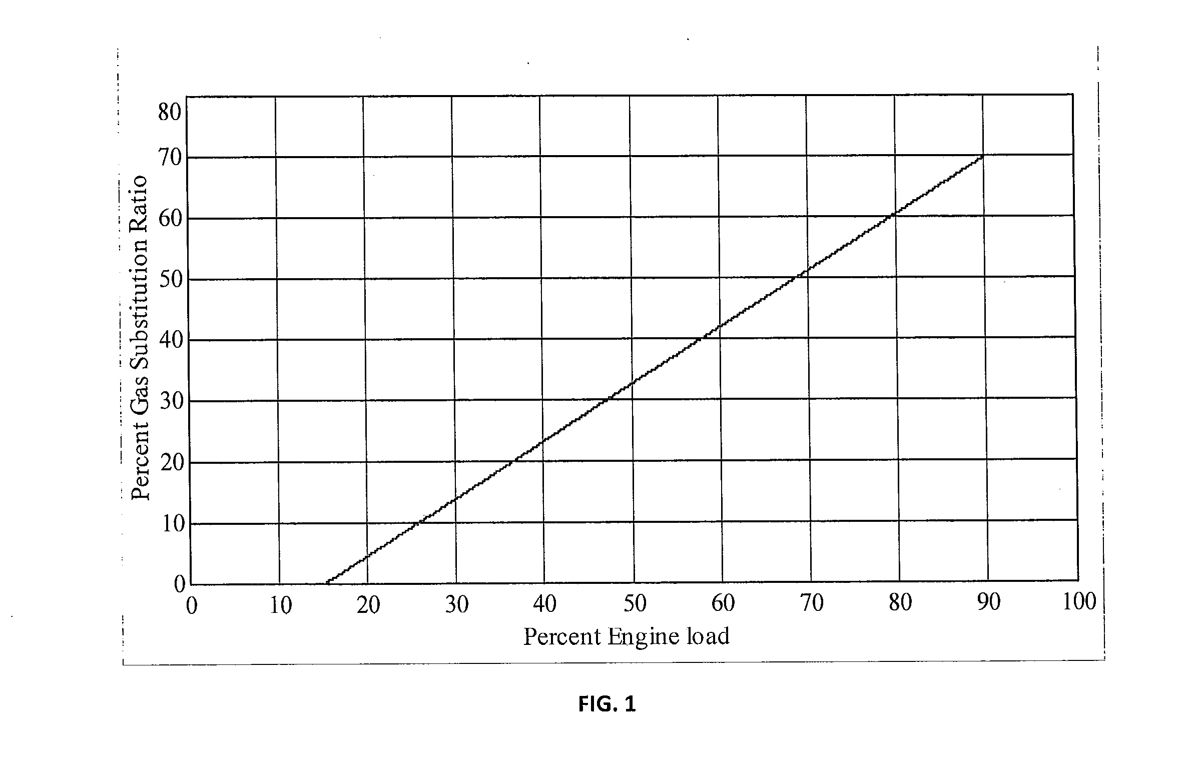
[0025]Certain embodiments as disclosed herein provide for a system and method for controlling the ratio of gas flow to total fuel flow or the gas substitution ratio (GSR) in a bi-fuel engine independent of any load sensing. Because of the fact that the control of non-generator loads can be difficult without direct torque sensing, any scheme that obviates the need for load sensing altogether is attractive.

[0026]After reading this description it will become apparent to one skilled in the art how to implement the invention in various alternative embodiments and alternative applications. However, although various embodiments of the present invention will be described herein, it is understood that these embodiments are presented by way of example only, and not limitation.

[0027]The allowable ratio of gas flow to total fuel flow (gas substitution ratio, GSR) in a bi-fuel or duel fuel engine is largely a function of engine load. At low loads, low diesel or non-gaseous fuel flow and low asso...


PUM


Abstract

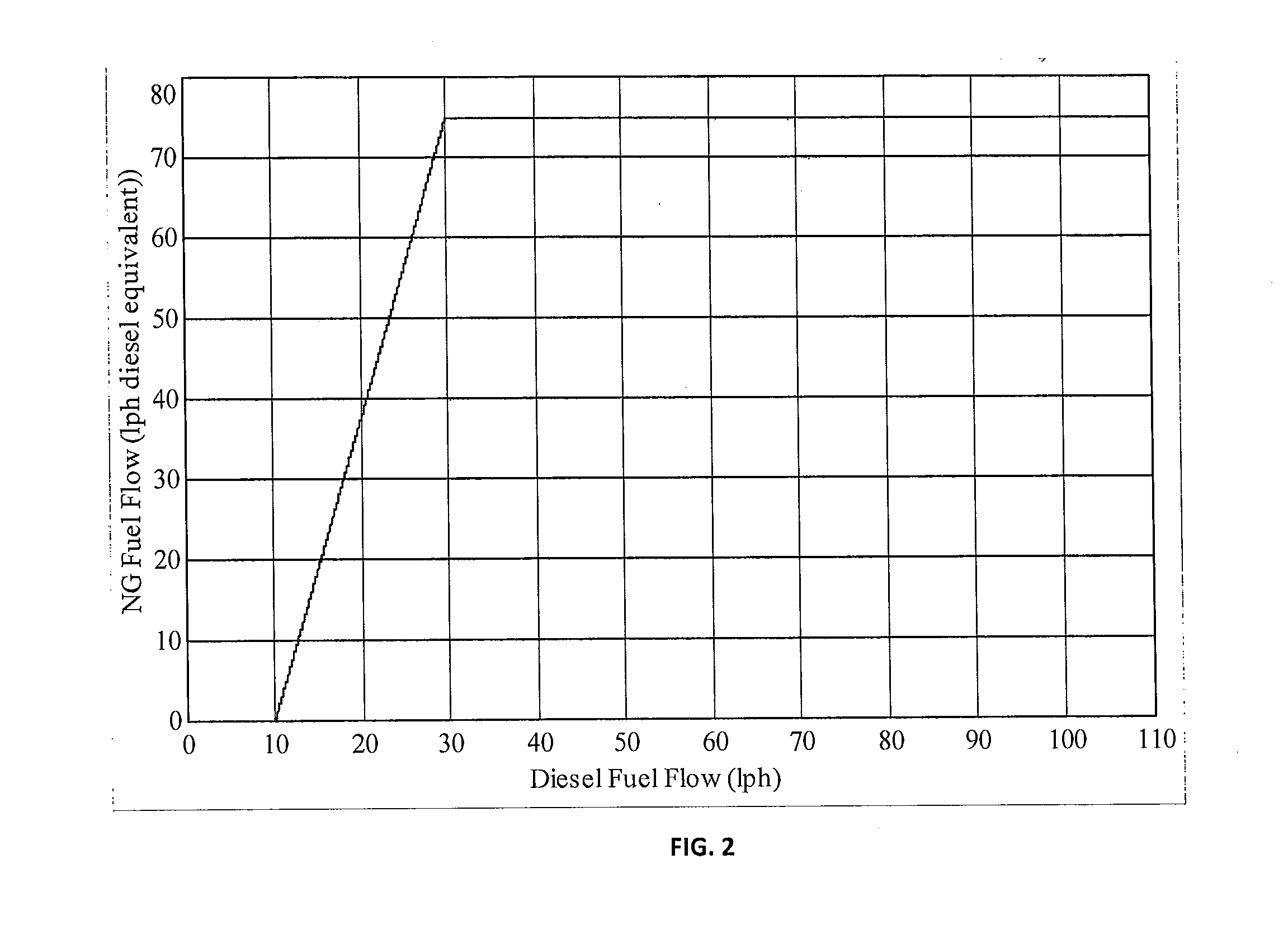
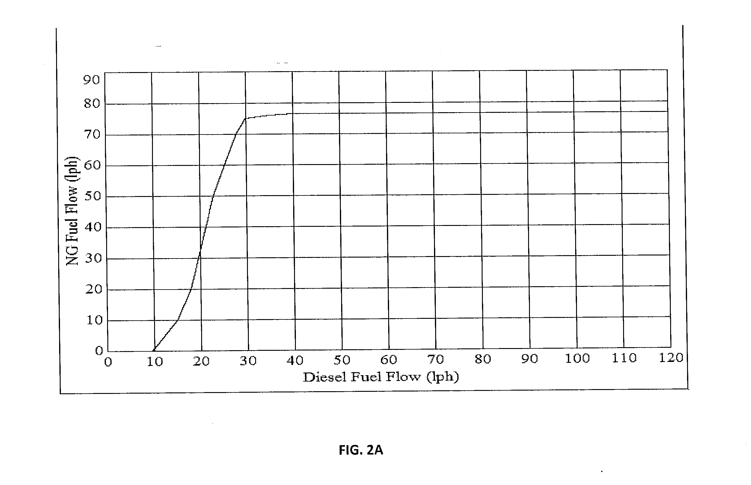
A gas substitution ratio control system varies natural gas flow to a bi-fuel engine based on detected diesel flow to maintain a desired gas substitution ratio (GSR), without any requirement to sense engine load. In other words, GSR is controlled without monitoring engine load level. In one system, an engine is first calibrated to map actual gas and diesel flows to provide the correct GSR for all engine loads. The calibration data is then stored and diesel flow rate is monitored. The current detected diesel flow rate is used to determine the required gas flow rate for correct GSR. Gas flow to the engine is then adjusted to correspond to the required gas flow rate. Other embodiments meter gas to maintain the diesel flow rate at the same minimum level for all loads, or meter gas and diesel fuel flows to match a map of the limiting fuel energy based GSR (gas fuel energy rate / total fuel energy rate) at all loads for each engine model.

Description

BACKGROUND[0001]1. Field of the Invention[0002]This invention relates generally to bi-fuel engines in which two different fuels are injected into the combustion chamber, for example a gaseous fuel (NG) and a diesel fuel.[0003]2. Related Art[0004]The allowable ratio of gas flow to total fuel flow (gas substitution ratio, GSR) in a bi-fuel or dual fuel engine is largely a function of engine load. At low loads, low diesel flow and low associated combustion temperatures require that gas flow be zero to prevent engine misfiring. As load is increased, gas flow can be correspondingly increased to approximately 70% of total fuel flow at 100% engine load.[0005]In applications where load can be sensed, the GSR is controlled by scheduling NG flow as a function of load to produce the desired GSR. Some prior gas substitution systems (GSSs) employ load sensing and vary the GSR based on detected load. These all must be adaptable to a wide variety of driven equipment loads. Electrical generator loa...

Claims


Application Information

Patent Timeline
Patent Type & Authority Applications(United States)
IPC IPC(8): F02D19/08
CPCF02D19/081F02D19/0628F02D19/0647F02D19/0607F02D41/08F02D41/2438F02D41/2454F02D41/2461F02D41/2467F02D41/247F02D41/3094F02D41/0025F02D2200/1015F02D41/0027F02M21/0215Y02T10/30F02B43/12F02B2043/103F02D41/26
Inventor FISHER, C. ROSSMANSFIELD, GEORGE A.FISHER, DAVID G.YATES, KRISTIAN W.ZAHIR, HELALLAUR, GALINAGRIMES, III, HILLARY H.
Owner CONTINENTAL CONTROLS CORP
Learn More