
Sewage treatment system

a sewage treatment system and sewage technology, applied in biological water/sewage treatment, separation processes, filtration separation, etc., can solve the problems of high electricity bill of sewage treatment, high cost of sludge treatment, and high cost of sewage treatmen

Active Publication Date: 2014-03-20
METAWATER CO LTD
View PDF5 Cites 10 Cited by
  • Summary
  • Abstract
  • Description
  • Claims
  • Application Information

AI Technical Summary

Benefits of technology

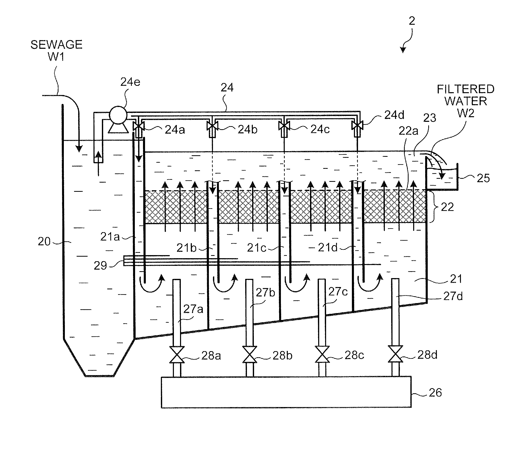
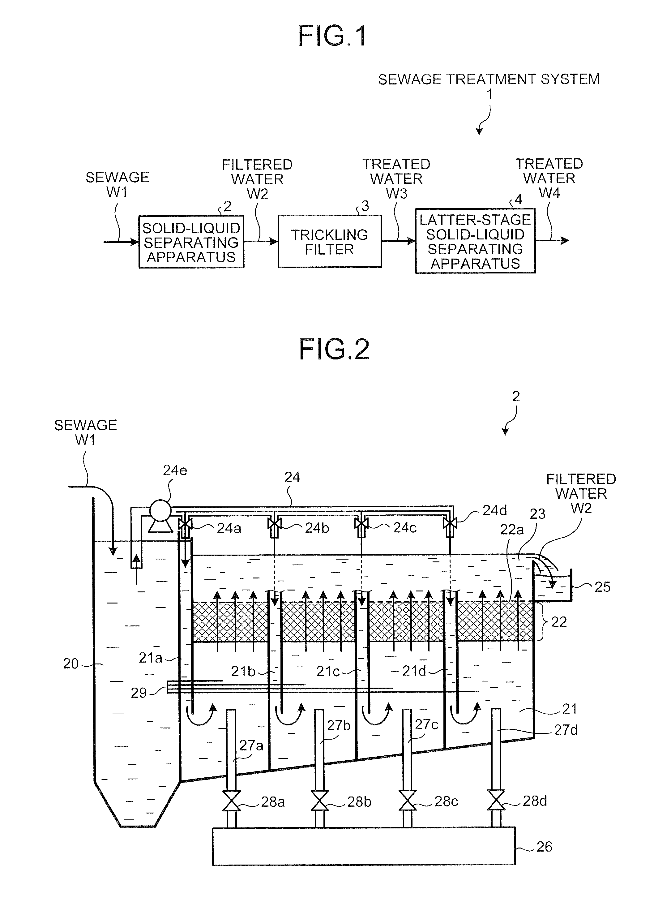
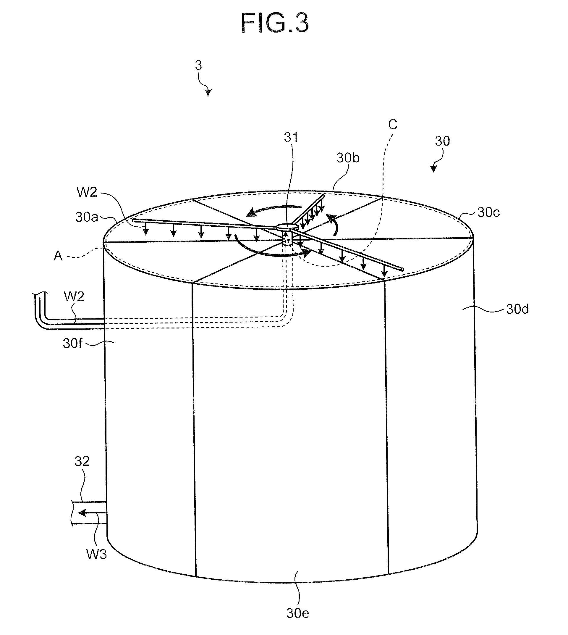
The sewage treatment system in this patent includes two main components: a solid-liquid separating apparatus and a trickling filter. The solid-liquid separating apparatus uses a packed layer of filtering medium to separate sewage into solid components and filtered water, with the filtered water flowing out the top. The trickling filter uses a layer of filtering medium with microorganisms attached to it to further biotreat the filtered water. This system effectively treats sewage by separating and purifying it, resulting in cleaner water.

Problems solved by technology

However, in the sewage treatment system by the standard activated sludge method, since a lot of power is consumed for the aeration treatment, an electric bill for the sewage treatment is high.
Further, much cost is required to treat sludge which is generated during the sewage treatment.
As a result, in the sewage treatment system by the standard activated sludge method, a running cost in the sewage treatment is expensive as compared with other methods.
Further, in the standard activated sludge method, sludge in a precipitation basin is difficult to precipitate, and as a result, a bulking phenomenon in which sludge, and the like leak from the precipitation basin occurs.
However, in the sewage treatment system by the anaerobic lagoon method, since it is difficult to reduce a biochemical oxygen demand (BOD) of the sewage to be treated, rivers or sea may be contaminated.
Since the sludge generated in the lagoon may not be extracted, the sludge is deposited in the lagoon, and as a result, a reduction rate of the BOD further deteriorates.
When the sludge is excessively deposited, a sewage treatment capability in the lagoon deteriorates and finally, the sewage may not be treated in the same lagoon.
Also, since the concentration of suspended solids (SS) of sewage to be treated, which are introduced into the trickling filter from the first precipitation basin, is high, a trickling nozzle is often clogged.
Further, in the first precipitation basin at the former stage of the trickling filter, fine SS or solid BOD of the sewage to be treated is not sufficiently removed, and as a result, garbage including solids, and the like which may not be fully separated from the first precipitation basin is retained in the filtering medium layer of the trickling filter and bad smell occurs due to corruption of the retained garbage or filtering flies are caused due to the retained garbage.

Method used


Image

  • Sewage treatment system
  • Sewage treatment system
  • Sewage treatment system

Examples


modified example

[0145]Subsequently, a modified example of the trickling filter 3 will be described. The trickling filter 3 in the first and second embodiments of the present invention allows the washing drainage water to flows out free from the washing drainage pipe opened by the valve, but in the modified example of the trickling filter 3, the trickling filter allows the washing drainage water to be discharged by using a siphon principle. FIG. 12 is a schematic diagram illustrating a modified example of the trickling filter in the present invention. As illustrated in FIG. 12, the trickling filter according to the modified example includes a washing drainage pipe 39c instead of the washing drainage pipe 39a and the valve 39b in the first and second embodiments. Other components are the same as those of the first and second embodiments and the same reference numerals refer to the same components.

[0146]That is, a filter body of the trickling filter according to the modified example is constituted by ...


PUM

PropertyMeasurementUnit
Speedaaaaaaaaaa
Shapeaaaaaaaaaa

Abstract

A sewage treatment system, includes a solid-liquid separating apparatus having a first filtering medium packed layer packed with a predetermined filtering medium, configured to separate sewage to be treated into solid components and filtered water by passing the sewage through the first filtering medium packed layer upward, and configured to reversely wash the first filtering medium packed layer by passing the filtered water through the first filtering medium packed layer downward at a predetermining timing; and a trickling filter installed on a latter stage of the solid-liquid separating apparatus, having a second filtering medium packed layer packed with a filtering medium attached with microorganisms, and configured to allow the filtered water to fall into the second filtering medium packed layer by trickling the filtered water onto an upper part of the second filtering medium packed layer to flow out treated water acquired by biotreating the filtered water by the microorganisms.

Description

CROSS-REFERENCE TO RELATED APPLICATION[0001]This application is a continuation of PCT International Application No. PCT / JP2012 / 063649 filed on May 28, 2012 which claims the benefit of priority from Japanese Patent Application No. 2011-118401 filed on May 26, 2011, the entire contents of which are incorporated herein by reference.BACKGROUND OF THE INVENTION[0002]1. Field of the Invention[0003]The present invention relates to a sewage treatment system that treats sewage.[0004]2. Description of the Related Art[0005]In the related art, as a sewage treatment system that treats sewage such as living drainage water or factory drainage water, various sewage treatment systems have been put to practical use, such as a system by a standard activated sludge method, a system by an anaerobic lagoon method, or a system by a trickling filter method.[0006]In the sewage treatment system by the standard activated sludge method, an aeration treatment is performed, which supplies oxygen to a large varie...

Claims


Application Information

Patent Timeline
IPC IPC(8): C02F3/04B01D29/66
CPCB01D29/66C02F3/04C02F3/06C02F3/085C02F3/006C02F3/043C02F3/105C02F2209/001C02F2209/44C02F2303/16Y02W10/10
Inventor MIYATA, ATSUSHITAKEDA, SHIGEKIKURUMA, TETSUTAROU
Owner METAWATER CO LTD
Learn More