Gutter profile and aircraft

a technology for aircraft and gutters, applied in aircraft accessories, fuselages, transportation and packaging, etc., can solve the problems of affecting the flow of aircraft, so as to reduce the drain cross-section in flight and optimise the flow behaviour

Active Publication Date: 2014-03-20
AIRBUS OPERATIONS GMBH
View PDF3 Cites 2 Cited by
  • Summary
  • Abstract
  • Description
  • Claims
  • Application Information

AI Technical Summary

Benefits of technology

[0004]It is the object of the invention to provide a gutter profile for draining liquids on an aircraft which eliminates the aforesaid disadvantages and automatically reduces its drain cross-section in flight, and to provide an aircraft having an optimised flow behaviour.
[0006]With increasing aircraft speed and therefore with increasing inflow pressure on the flow guiding device, said flow guiding device brings about an automatic contact of the drain section against the connecting section or the fuselage outer skin, whereby the gutter profile no longer projects so far into the air flow and less perturbing flow turbulence is formed. The pre-tensioning of the drain section thereby ensures that when the inflow pressure is reduced and therefore on the ground, the gutter profile opens automatically and liquids are channelled off
[0008]In order to ensure a harmonic load distribution of the drain cross-section, it is advantageous if the flow guiding device has a plurality of guiding elements, which are disposed on an outer surface of the drain section facing away from the connecting section.
[0013]A preferred aircraft is provided with respectively one gutter profile according to the invention at least in the area of its passenger doors. Such an aircraft is characterised by an optimised surface or outer flow, a reduced fuel consumption and by reduced external noise.

Problems solved by technology

However, since the gutter profiles are fixed externally on the aircraft fuselage, they project into the air flow and cause perturbing flow turbulence.
It has been shown however that in the event of vibrations and / or air flows, the cover section tends to hit against the fuselage with the result that, inter alia, the fuselage and the cover section become damaged.

Method used


Image

  • Gutter profile and aircraft
  • Gutter profile and aircraft
  • Gutter profile and aircraft

Examples


Embodiment Construction

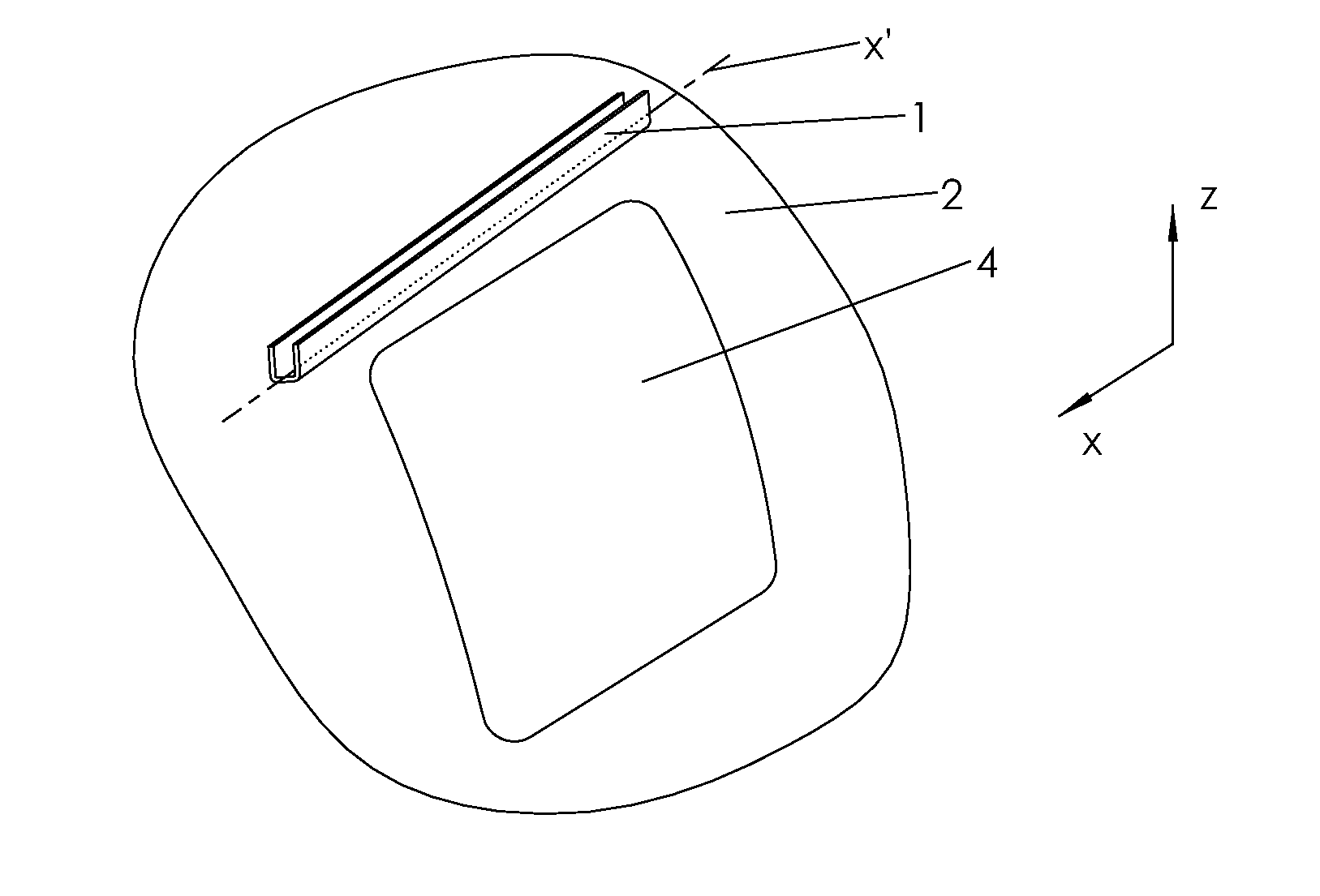
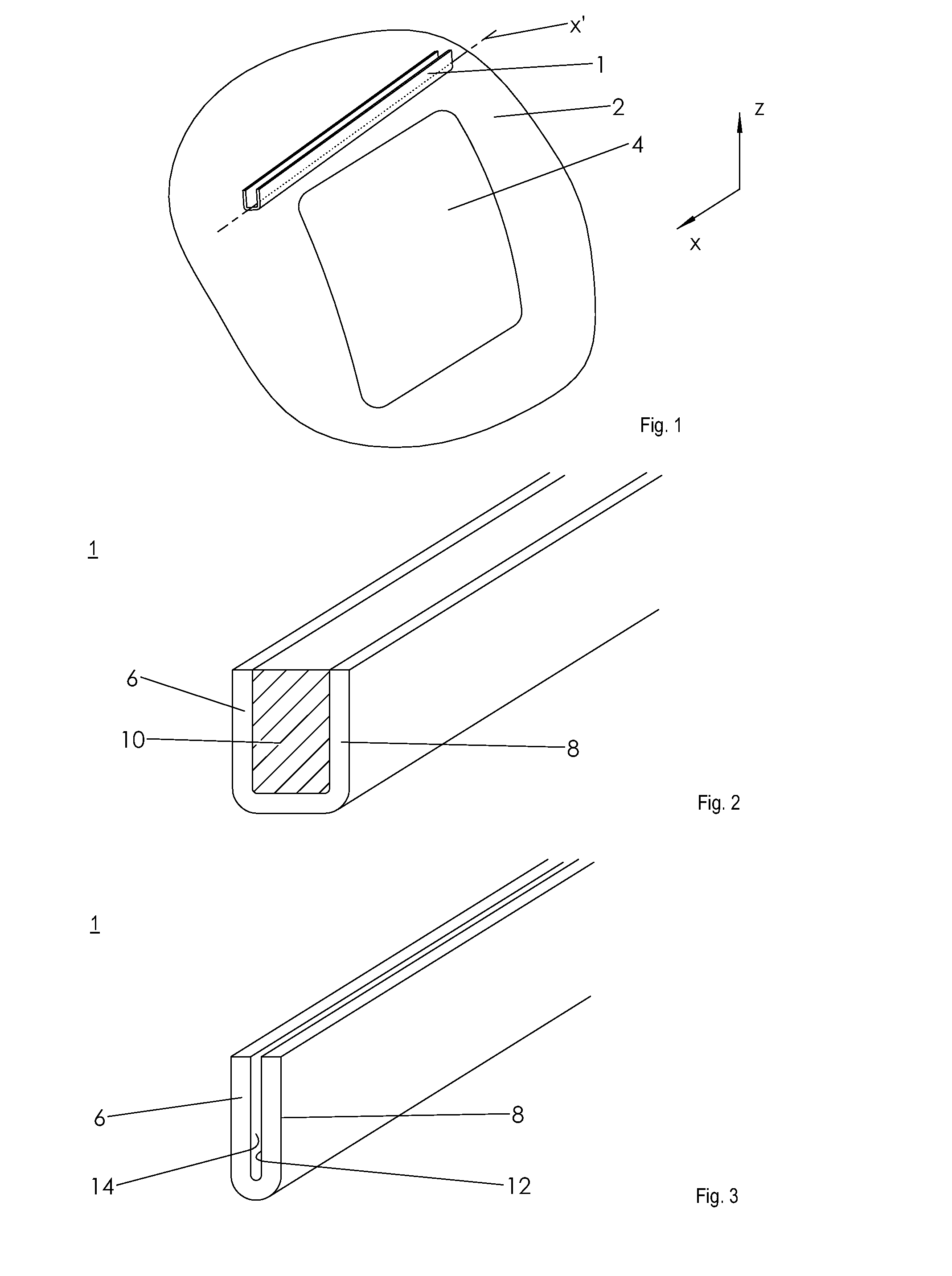
[0023]FIG. 1 shows a highly simplified diagram of a gutter profile 1 for draining liquids, which is inclined on a fuselage section 2 of an aircraft with respect to the longitudinal direction x and is disposed above a passenger door 4 when viewed in the vertical direction z. The gutter profile 1 is thereby inclined with its profile longitudinal axis x′ with respect to the longitudinal axis x in such a manner that it runs in the direction of an outer flow or air flow in flight.

[0024]According to FIG. 2, the gutter profile 1 is configured to be U-shaped with a strip-like connecting section 6 for connecting the gutter profile 1 to the fuselage section 2 and having an L-shaped drain section 8 for defining a drain cross section 10 shown hatched. Naturally, other profiles such as a V-profile are also conceivable. The gutter profile 1 is preferably formed in one piece and consists of a plastic material, which is preferably fibre-reinforced. However, it can also be metallic. However, at leas...


PUM


Abstract

A gutter profile for draining liquids on an aircraft, comprising a connecting section for connecting the gutter profile to an outer skin of the aircraft and comprising a drain section for forming a drain cross-section of the gutter profile. The drain section is pre-tensioned into a ground position which opens the drain cross-section and has a flow guiding device for transferring the drain section into a flight position which closes the drain cross-section. An aircraft having such a gutter profile is also disclosed.

Description

CROSS-REFERENCES TO RELATED APPLICATIONS[0001]This application claims the benefit of the U.S. Provisional Application No. 61 / 485,152, filed on May 12, 2011, and of the German patent application No. 10 2011 075 772.4 filed on May 12, 2011, the entire disclosures of which are incorporated herein by way of reference.BACKGROUND OF THE INVENTION[0002]The invention relates to a gutter profile for the draining of liquids on an aircraft and an aircraft having such a gutter profile.[0003]Gutter profiles for the draining of liquids in passenger aircraft are usually fixed above doors on a fuselage section. They are intended to guide liquids such as rainwater, condensation water, de-icing agents and the like laterally past the doors and thereby prevent any ingress of liquid into the door opening. However, since the gutter profiles are fixed externally on the aircraft fuselage, they project into the air flow and cause perturbing flow turbulence. In order to reduce flow turbulence, it is suggeste...

Claims


Application Information

Patent Timeline
Patent Type & Authority Applications(United States)
IPC IPC(8): B64C1/14
CPCB64C1/1461B64C1/14
Inventor GENSCH, HINNIKKIRSTEIN, HAUKE
Owner AIRBUS OPERATIONS GMBH
Why Eureka
Try Eureka