
Eureka
For R&D, Eureka makes reading and utilizing patents & technical documents easy.
Eureka AIR
Designed for self-driven R&D workflows. Generate viable solutions, solve complex R&D challenges, empower your innovation with AI.

Eureka Materials
Designed for material experts only. Revolutionize your material R&D, from search, analyze, to developing new materials.

TechResearch
Generate reliable direction feasibility study reports for your R&D in just a few steps.

TechSeek
Discover and master advanced knowledge NOW. Basics, ideas, possibilities, all at once.

TechMind
As an expert in R&D Theories, TechMind can generates customized viable solutions instantly.

TechRisk
Analyze your overall solution with one click, know your potential R&D risks in advance.

TechMonitor
Get weekly tech updates, stay abreast of the latest tech innovations and key insights.
Electrostatic lens unit
a technology of electrostatic lens and lens body, which is applied in the direction of instruments, beam deviation/focusing by electric/magnetic means, mass spectometers, etc., can solve the problems of out-of-focus of charged particle beams, blurred images, and risk of contact between electrostatic lens and exposure substra
- Summary
- Abstract
- Description
- Claims
- Application Information
AI Technical Summary
Benefits of technology
Problems solved by technology
Method used
Image

Examples
first embodiment
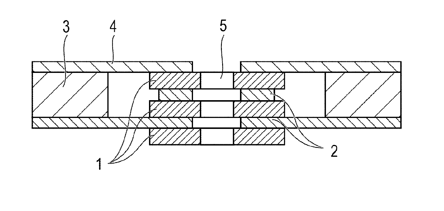
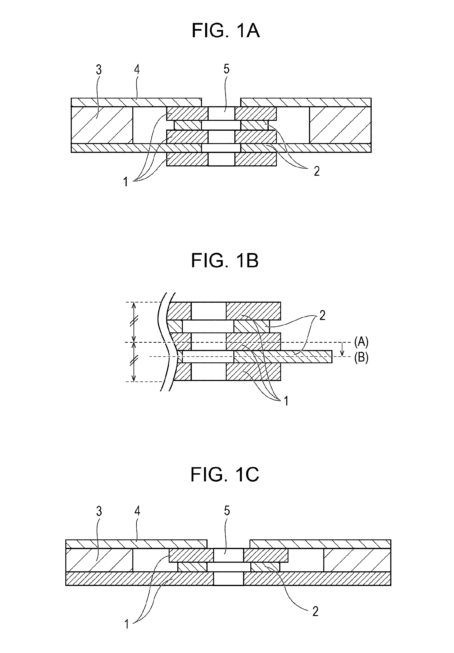
[0017]FIGS. 1A to 1C are a schematic cross-sectional view of a charged particle radiation lens (hereinafter referred to as an electrostatic lens) unit according to the first embodiment. The electrostatic lens includes two or more plate-shaped electrodes 1 arranged apart from each other and one or more plate-shaped spacing members 2 disposed therebetween and configured to define the distance between the electrodes. The electrodes 1 are formed of a metal or a semiconductor. The spacing member 2 is formed of glass or ceramic. A fixing member 3 is formed of a metal, a semiconductor, glass, or ceramic. A supporting member 4 is formed of a metal, a semiconductor, glass, or ceramic. As illustrated in FIG. 1A, the electrodes 1 and the spacing members 2 are formed with through holes 5 through which a charged beam passes. The charged beam is discharged from a charged particle radiation source, not illustrated, and composed of charged particles. Through hole arrays composed of a plurality of t...
second embodiment
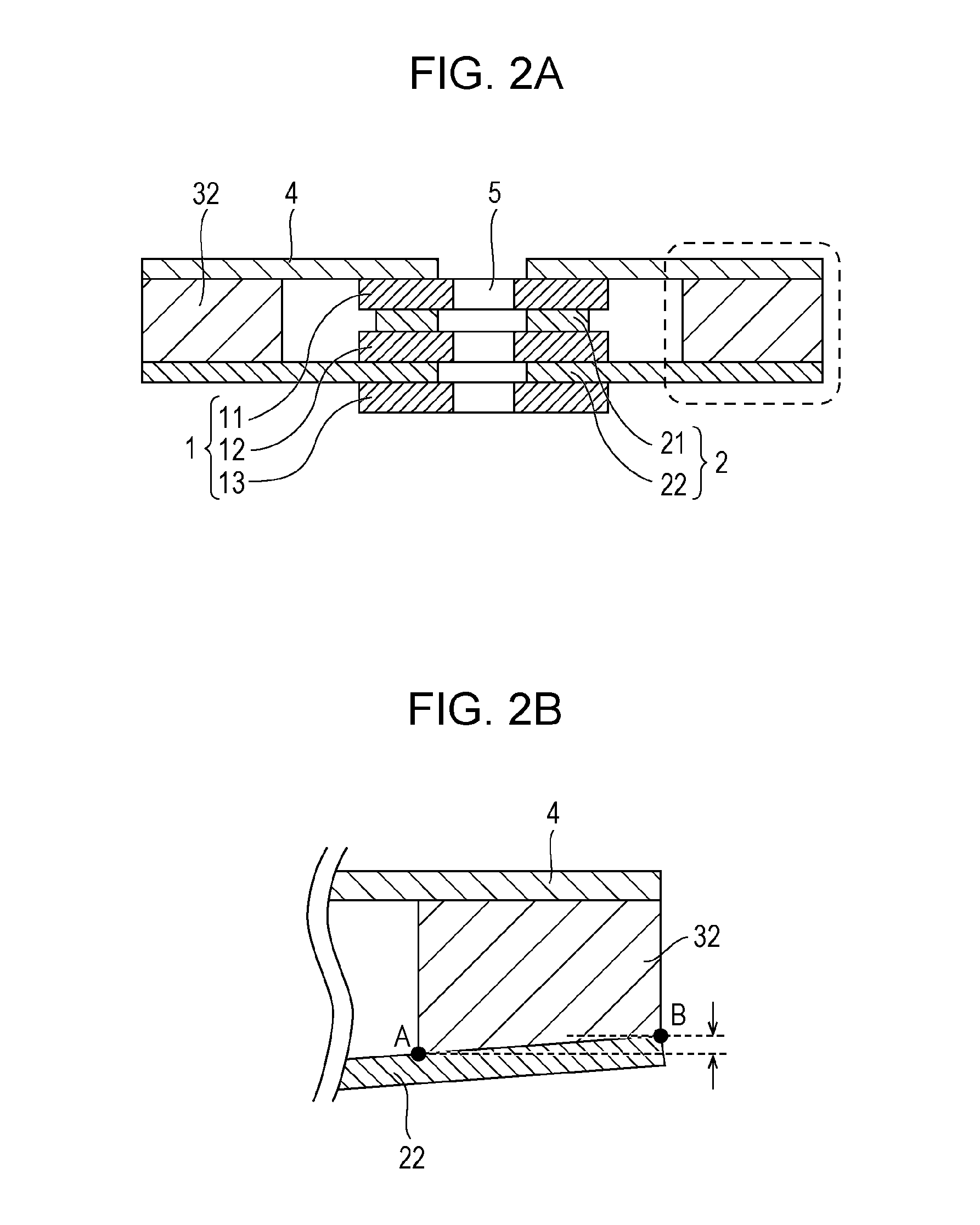
[0019]FIG. 2A is a cross-sectional view of an electrostatic lens of a second embodiment. FIG. 2B is an enlarged view of an area surrounded by a broken line in FIG. 2A. As illustrated in FIG. 2B, the bottom surface of a fixing member 32 (the surface connected to a spacing member 22) is inclined in advance with respect to a horizontal plane (a plane having a normal line coincident with the optical axis). The electrostatic lens has a strain originated from a point A. If the point A is located on an upper side of a point B, the electrostatic lens is deformed into an upward projecting shape, and if the point A is located on a lower side of the point B, the electrostatic lens is deformed into a downward projecting shape. By applying the strain caused by the deformation of the electrostatic lens in the direction opposite to the direction of thermal deformation by the reflected charged particles, the amount of deformation of the lens caused by a heat generation is cancelled. Therefore, the ...
third embodiment
[0020]Although the basic configuration is the same as the first embodiment, the connection between the supporting member 4 and an electrode 11 is achieved by bonding. When the supporting member 4 and the electrode 11 are connected directly, the same material as the electrode 11 is selected and used for the supporting member 4. In contrast, when an intermediate member (not illustrated) is interposed therebetween, a material having a coefficient of linear expansion larger than that of the intermediate member is selected and used for the supporting member 4. When the electrostatic lens generates heat, the heat is transferred to the supporting member 4 via the lens. The supporting member 4, and the electrode 11 or the intermediate member are thermally expanded in the horizontal direction. However, the supporting member 4 expands to a larger extent due to the difference in coefficient of linear expansion (linear expansion coefficient). At this time, since the both materials are bonded, a...
PUM
 Abstract
Description
Claims
Application Information
 - R&D Engineer
- R&D Manager
- IP Professional
- Industry Leading Data Capabilities
- Powerful AI technology
- Patent DNA Extraction
Browse by: Latest US Patents, China's latest patents, Technical Efficacy Thesaurus, Application Domain, Technology Topic, Popular Technical Reports.
© 2024 PatSnap. All rights reserved.Legal|Privacy policy|Modern Slavery Act Transparency Statement|Sitemap|About US| Contact US: help@patsnap.com