This helps you quickly interpret patents by identifying the three key elements:
Problems solved by technology
Method used
Benefits of technology
Problems solved by technology
Because a top under bump metallurgy (UBM) is closer to a neighboring joint Cu trace, ther
Method used
Image
Click on the blue label to locate the original text in one second.
Reading with bidirectional positioning of images and text.
Examples
Embodiment Construction
[0011]The making and using of the presently preferred embodiments are discussed in detail below. It should be appreciated, however, that the present disclosure provides many applicable inventive concepts that can be embodied in a wide variety of specific contexts. The specific embodiments discussed are merely illustrative and do not limit the scope of the disclosure.
[0012]The present disclosure will be described with respect to preferred embodiments in a specific context, namely a ladder bump structure for a bump on trace (BOT) assembly. The concepts in the disclosure may also apply, however, to other semiconductor structures or circuits.
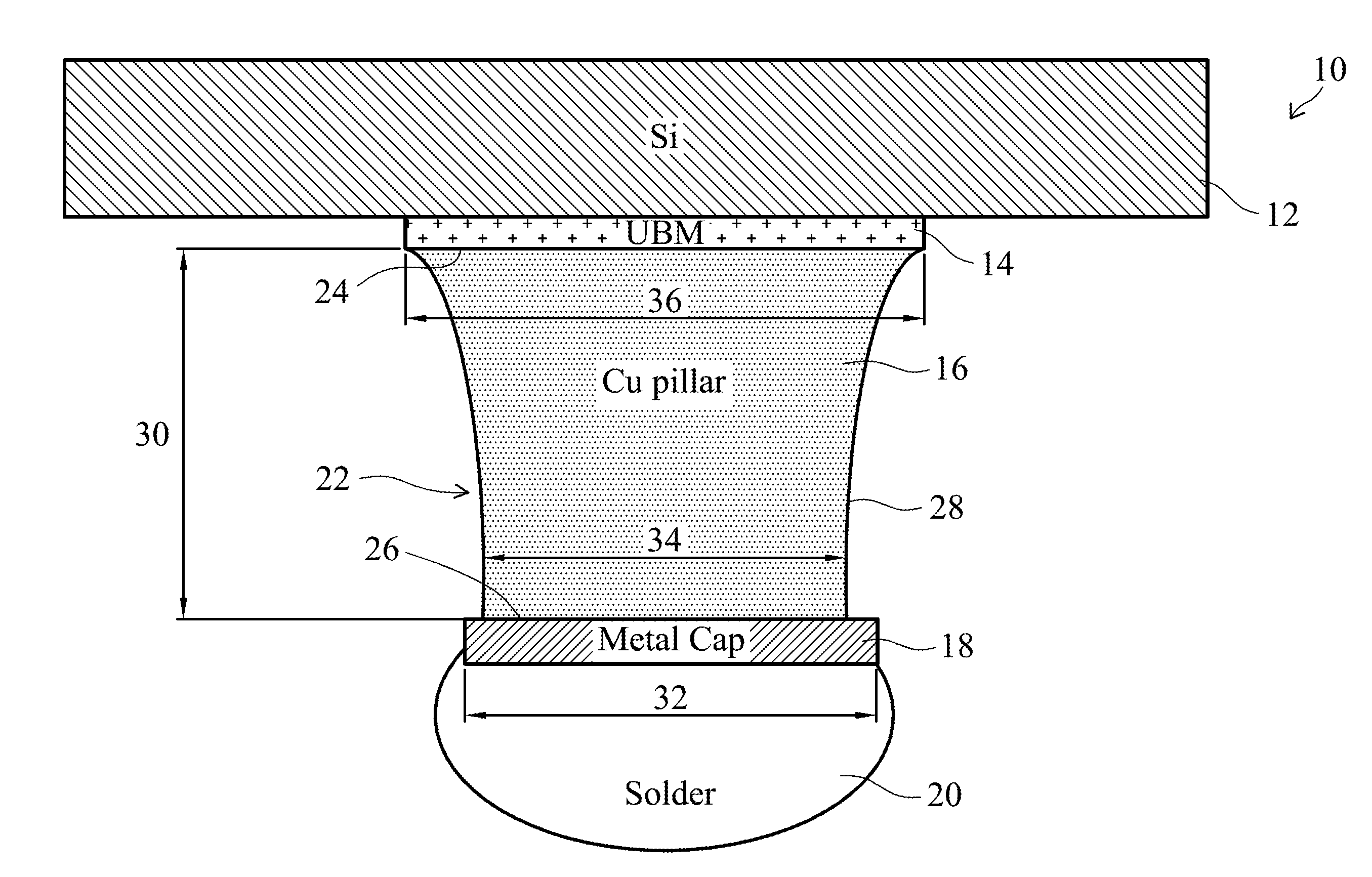
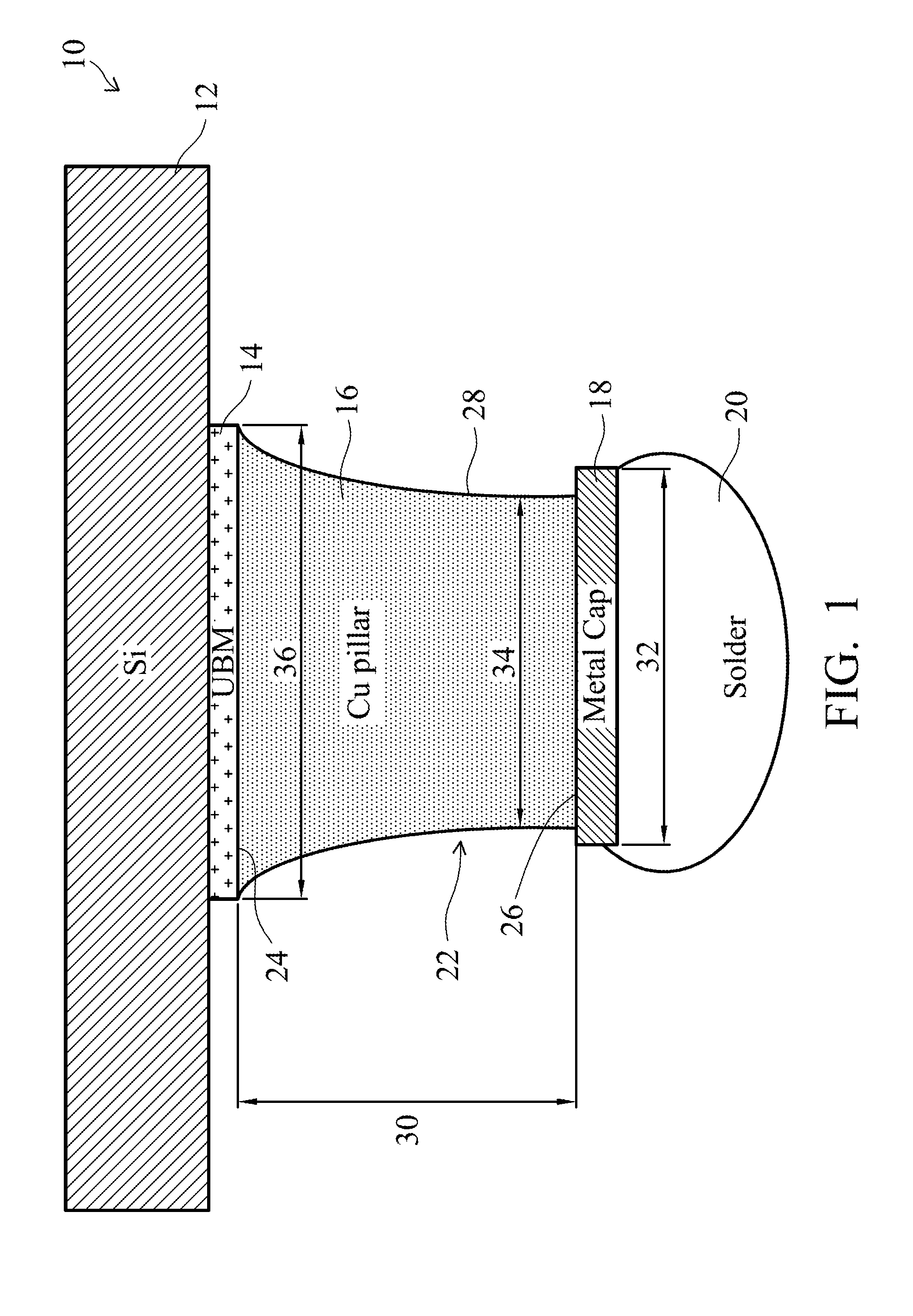
[0013]Referring now to FIG. 1, an embodiment ladder bump structure 10 is illustrated. As shown, the ladder bump structure 10 includes a substrate 12, an under bump metallurgy (UBM) feature 14, a copper pillar 16, a metal cap 18, and a solder feature 20. The substrate 12 may be, for example, a silicon wafer or silicon-containing layer of material. In...
PUM
Property
Measurement
Unit
Structure
aaaaa
aaaaa
Length
aaaaa
aaaaa
Width
aaaaa
aaaaa
Abstract
An embodiment ladder bump structure includes an under bump metallurgy (UBM) feature supported by a substrate, a copper pillar mounted on the UBM feature, the copper pillar having a tapering curved profile, which has a larger bottom critical dimension (CD) than a top critical dimension (CD) in an embodiment, a metal cap mounted on the copper pillar, and a solder feature mounted on the metal cap.
Description
CROSS-REFERENCE TO RELATED APPLICATIONS[0001]This application claims the benefit of U.S. Provisional Application No. 61 / 702,624, filed on Sep. 18, 2012, entitled “Ladd Bump Structures and Methods of Making the Same,” of U.S. Provisional Application No. 61 / 707,644, filed on Sep. 28, 2012, entitled “Metal Bump and Method of Manufacturing Same,” of U.S. Provisional Application No. 61 / 707,609, filed on Sep. 28, 2012, entitled “Interconnection Structure Method of Forming Same,” and of U.S. Provisional Application No. 61 / 707,442, filed on Sep. 28, 2012, entitled “Bump Structure and Method of Forming Same,” which applications are hereby incorporated herein by reference.BACKGROUND[0002]In a typical copper (Cu) pillar bump process, solder with or without nickel (Ni) below always has a larger critical dimension (CD) than the bottom of the Cu pillar, due to Cu over etching. This large top and small bottom bump profile is critical for fine pitch assembly yield, especially in bump on trace (BOT)...
Claims
Application Information
Patent Timeline
Application Date:The date an application was filed.
Publication Date:The date a patent or application was officially published.
First Publication Date:The earliest publication date of a patent with the same application number.
Issue Date:Publication date of the patent grant document.
PCT Entry Date:The Entry date of PCT National Phase.
Estimated Expiry Date:The statutory expiry date of a patent right according to the Patent Law, and it is the longest term of protection that the patent right can achieve without the termination of the patent right due to other reasons(Term extension factor has been taken into account ).
Invalid Date:Actual expiry date is based on effective date or publication date of legal transaction data of invalid patent.