Laser Scanner

a laser scanner and scanner body technology, applied in the field of laser scanners, can solve the problems of occupying a large amount of storage spa

Active Publication Date: 2014-03-20
FARO TECH INC
View PDF5 Cites 118 Cited by
  • Summary
  • Abstract
  • Description
  • Claims
  • Application Information

AI Technical Summary

Benefits of technology

[0045]FIG. 10 is an illustration of the scanned volume having areas having a high information content profile and areas having a low information content;

Problems solved by technology

Many of these surface points may not be needed in order to adequately represent objects or surfaces within the scanned volume.
However, a large amount of storage space may be taken up in the scanner's local storage device by extraneous data acquired during operation.
In addition, there is a tradeoff between scanning speed and resolution of collected 3D measurement values.

Method used


Image

  • Laser Scanner
  • Laser Scanner
  • Laser Scanner

Examples


Embodiment Construction

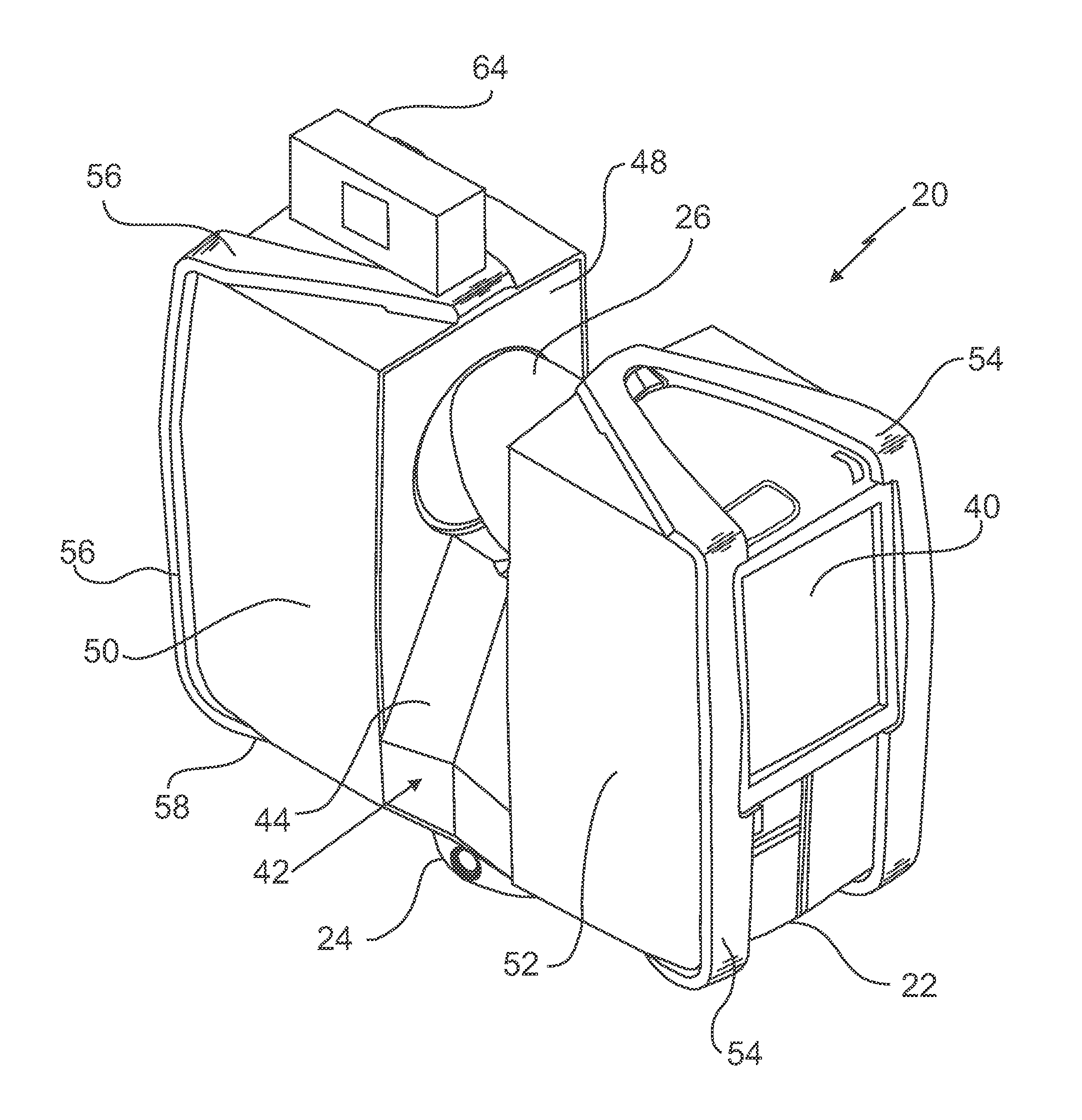
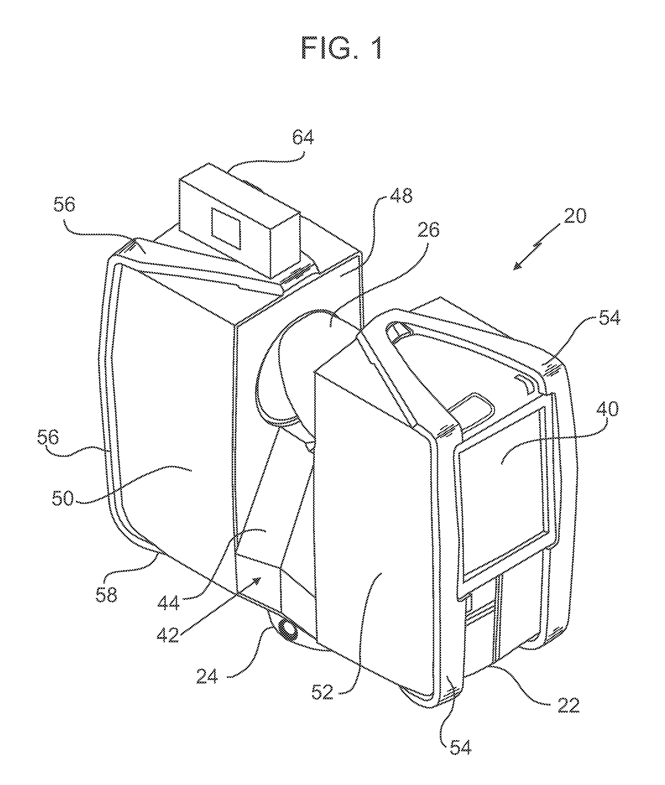
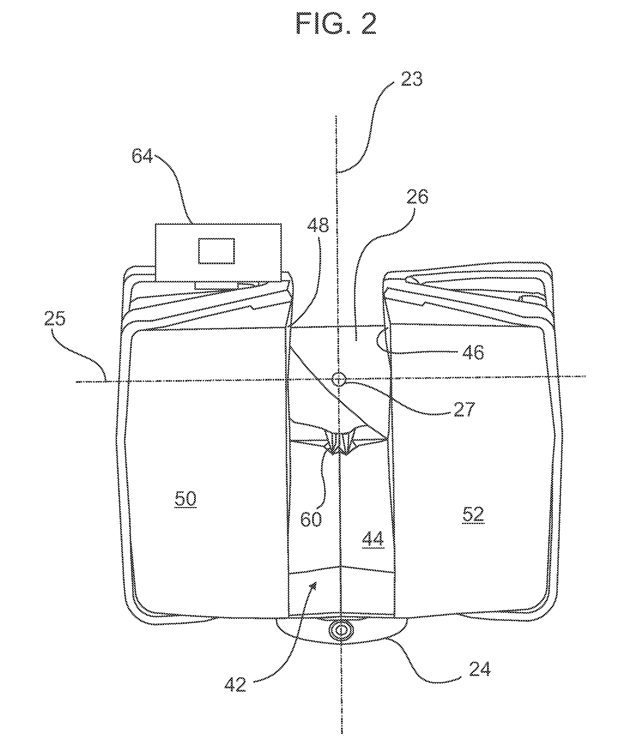
[0051]Embodiments of the present invention provide for a laser scanner device that may acquire data on the three-dimensional (3D) coordinates of surface points in a scanned volume while having a variable surface point density or a variable scan speed, or both. Embodiments of the present invention provide advantages in reducing the amount of local storage needed while acquiring 3D coordinate data of surface points. Embodiments of the present invention provide advantages in reducing time to complete a measurement, time to graphically display an image of the acquired data, and memory used to store 3D data. In an embodiment, angular speed of a beam of light sent to a surface for 3D measurement is changed dynamically according to evaluation of the collected distances according to a quality factor, wherein the quality factor may depend on a variety of factors discussed herein. In an embodiment, the scanner includes a mirror rotated about a first axis and a second axis, with the scan rates...


PUM


Abstract

A method of dynamically adjusting an angular speed of a light beam emitted by a scanner in measuring three-dimensional (3D) coordinates of a surface or of dynamically adjusting an acquisition rate of 3D coordinates of a surface.

Description

CROSS-REFERENCE TO RELATED APPLICATIONS[0001]The present application is a nonprovisional application of U.S. Provisional Application 61 / 701,021 filed on Sep. 14, 2012, the contents of which are incorporated herein in their entirety.BACKGROUND OF THE INVENTION[0002]The subject matter disclosed herein relates to a laser scanner and in particular to a laser scanner able to vary the density of the measured surface points based on characteristics of the surface geometry.[0003]Laser scanners are a type of device that utilize a coherent light source to measure and determine the three-dimensional coordinates of points on an object. Laser scanners are typically used for scanning closed or open spaces such as interior areas of buildings, industrial installations and tunnels. Laser scanners are used for many purposes, including industrial applications and accident reconstruction applications. A laser scanner can be used to optically scan and measure objects in a volume around the scanner throu...

Claims


Application Information

Patent Timeline
Patent Type & Authority Applications(United States)
IPC IPC(8): G01B11/00G01S17/89
CPCG01B11/002G01S7/4817G01S17/89G02B26/127G02B26/10
Inventor STEFFEY, KENNETHBECKER, REINHARDBECKER, BERND-DIETMARGITTINGER, JURGEN
Owner FARO TECH INC
Why Eureka
Try Eureka