Plastic film
- Summary
- Abstract
- Description
- Claims
- Application Information
AI Technical Summary
Benefits of technology
Problems solved by technology
Method used
Image

Examples
Embodiment Construction
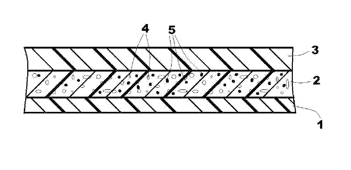
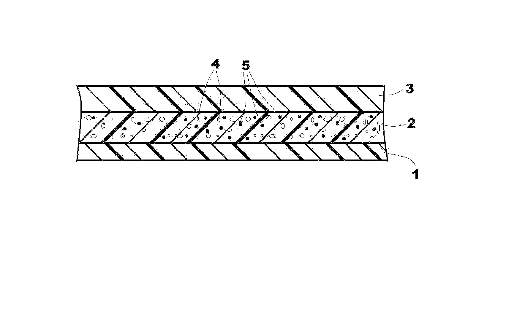
[0034]As seen in the drawing a foam has a base layer 1, a first layer 2, and a second layer 3. Cells or air bubbles in the first layer are shown at 5 and hard inorganic particulates at 6. The dimensions, compositions, and other properties of the layers 1, 2, and 3 are as shown in Tables 1 and 2 below.
[0035]According to a first embodiment a three-layered plastic film with an overall thickness of 100 μm and with a symmetrical layer structure was made by blown film coextrusion. According to Table 1 the two outer layers 1 and 3 are formed with a thickness of 15 μm from mixtures of polyethylene, with up to 60% by weight of these layers consisting of a low-density linear polyethylene (Bio-PE-LLD) formed substantially from renewable raw materials. The proportion of renewable raw materials (RRM) therein amounts to more than 80%. In addition to a low-density polyethylene formed from fossil raw materials, a white batch is provided with a proportion of 10% by weight for coloring. The densities...
PUM
| Property | Measurement | Unit |
|---|---|---|
| Fraction | aaaaa | aaaaa |
| Fraction | aaaaa | aaaaa |
| Thickness | aaaaa | aaaaa |
Abstract
Description
Claims
Application Information