Cutting or scoring balloon and apparatus therefor

Active Publication Date: 2014-03-27
COOK MEDICAL TECH LLC
View PDF7 Cites 21 Cited by
  • Summary
  • Abstract
  • Description
  • Claims
  • Application Information

AI Technical Summary

Benefits of technology

[0021]The apparatus and method provide a reliable system for ple

Problems solved by technology

In addition, this pleating and wrapping arrangement leaves the cutting or scoring

Method used


Image

  • Cutting or scoring balloon and apparatus therefor
  • Cutting or scoring balloon and apparatus therefor
  • Cutting or scoring balloon and apparatus therefor

Examples


Embodiment Construction

[0031]It is to be understood that the drawings are schematic and are not to scale.

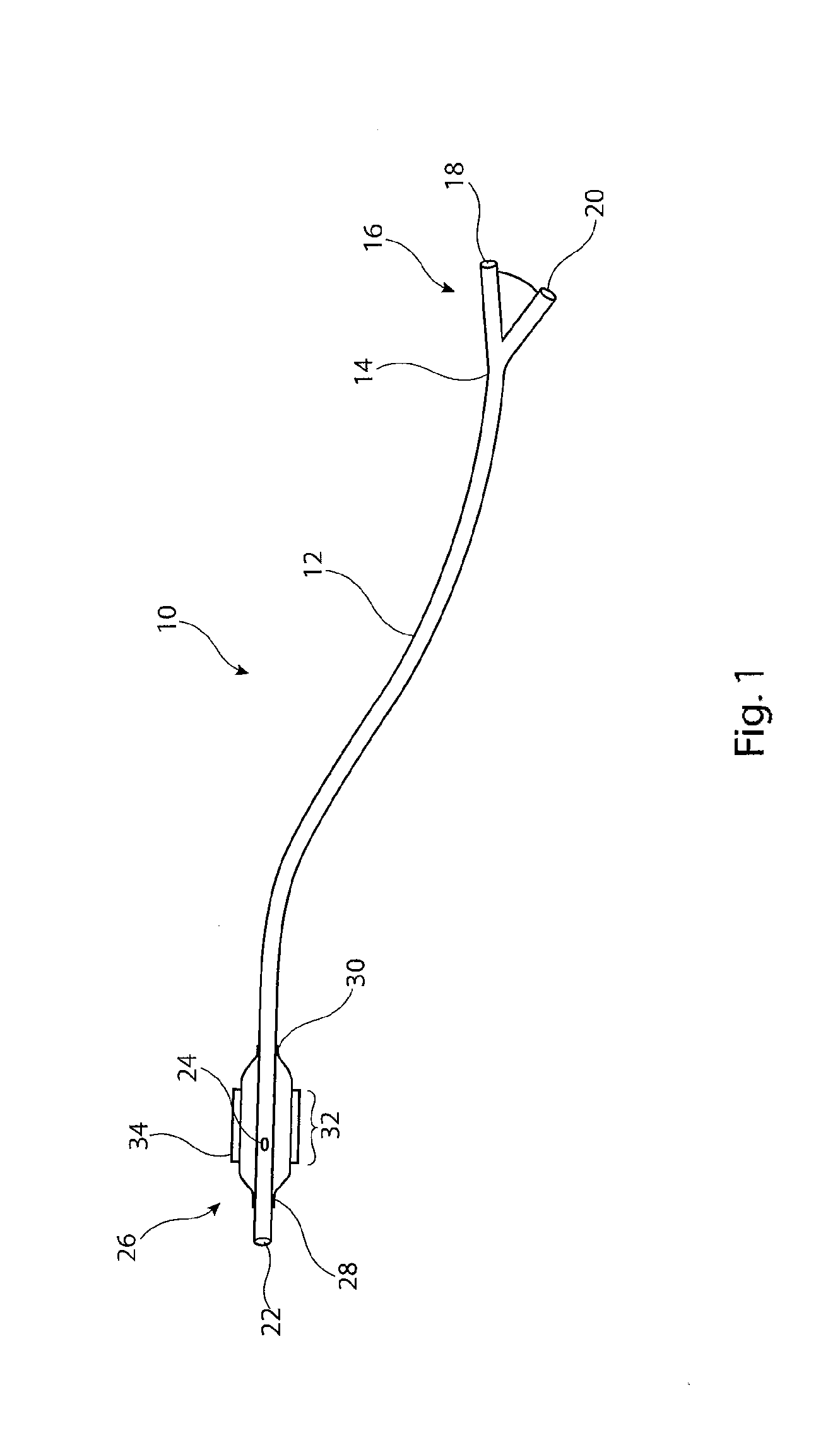
[0032]Referring to FIG. 1, there is shown in schematic form an example of cutting or scoring balloon catheter assembly 10 which has, in the inflated state shown in FIG. 1, a generally conventional structure. More specifically, the assembly 10 includes a catheter 12 having a proximal end 14 coupled to a fitting 16, which in this example is a Y-fitting. The fitting 16 includes a first port 18 for the passage of a guide wire and a second port 20 for feeding inflation fluid into the catheter 12. The catheter 12 typically has at least two lumens passing therethrough, one from the first port 18 all the way to the distal end 22 of the catheter 12, for receiving a guide wire. The second lumen extends from the port 20 to an opening 24 proximate the distal end 22 of the catheter.

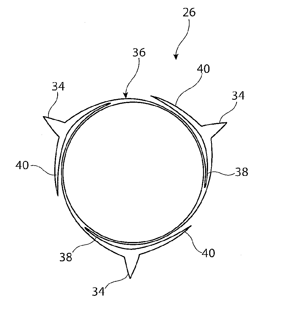
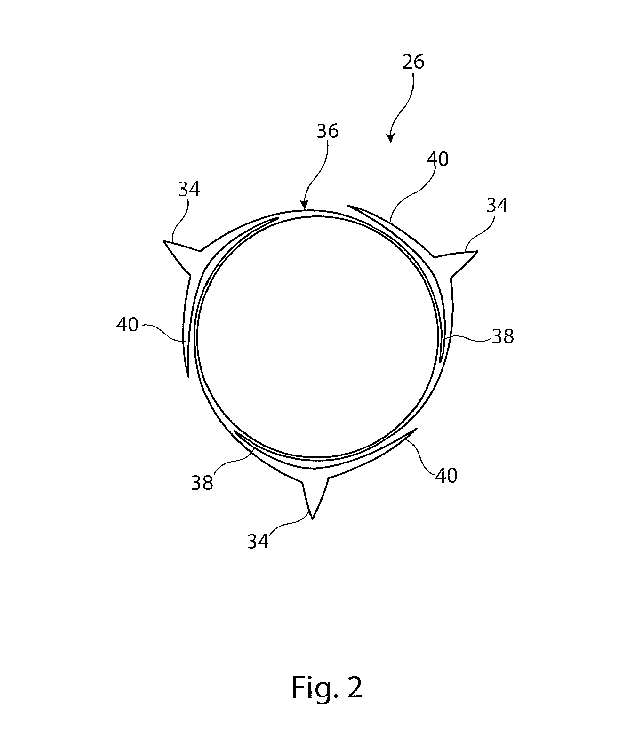
[0033]Attached to the distal end of the catheter is a cutting or scoring balloon 26, which at its ends 28 and 30 is fixed to the cathet...


PUM

PropertyMeasurementUnit
Flexibilityaaaaaaaaaa
Widthaaaaaaaaaa

Abstract

A cutting or scoring balloon (26) is provided with a plurality of cutting or scoring elements (34) and is wrapped onto a balloon catheter (12) such that the cutting or scoring elements (34) overlie the balloon wall (36) with the balloon wall (36) pleated underneath the cutting or scoring elements (34). The cutting or scoring elements (34) remain exposed when the balloon (26) is pleated and wrapped onto the balloon catheter (12) and in a tightly wrapped configuration.

Description

[0001]This application claims the benefit of the filing date of United Kingdom (GB) patent application number 1216965.2, filed Sep. 24, 2012, which is hereby incorporated by reference herein.TECHNICAL FIELD[0002]The present invention relates to a cutting or scoring balloon and to apparatus for and a method of pleating and wrapping such a balloon.BACKGROUND OF THE INVENTION[0003]Cutting or scoring balloons are known for opening occluded or constricted vessels of a patient, caused for instance by stenosis. Such balloons may have one or more blades or cutting elements fixed to or otherwise integral with the balloon wall, used for cutting or fragmenting stenosed material from the vessel wall. These balloons are generally effective in opening stenosed vessels. However, difficulties arise with the deployment of such balloons as a result of the risk of the balloon wall being cut or torn by the cutting or scoring elements. As a result, these balloons tend to be wrapped in such a manner that...

Claims


Application Information

Patent Timeline
IPC IPC(8): A61B17/3207
CPCA61B17/320725A61B2017/22061A61M25/1002A61M25/1038A61M2025/1004A61M2025/1086Y10T29/49
Inventor BURTON, DAVID G.ELGAARD, PER
Owner COOK MEDICAL TECH LLC
Why Eureka
Try Eureka