Bolt carrier and bolt for gas operated firearms

a gas-operated, bolt-carrying technology, applied in the direction of cartridge extractors, shoulder-fired small arms, weapons, etc., can solve the problems of insufficient torque applied to the screws, deficient methods, and insufficient aspiration firearms, so as to prevent the nozzle from loosening, and prolong the service life of the cotter pin

Active Publication Date: 2014-04-03
LWRC INTERNATIONAL
View PDF8 Cites 77 Cited by
  • Summary
  • Abstract
  • Description
  • Claims
  • Application Information

AI Technical Summary

Benefits of technology

[0026]The improved bolt carrier includes an integral gas key which is threaded to receive an extension nozzle which is constructed to receive a portion of the host firearm's gas tube. The extension nozzle is held in place through the use of a cross pin which prevents loosening of the nozzle during use of the firearm.
[0027]The present invention also provides an improved bolt carrier that includes a machined structure on the exterior of the bolt carrier which optimally orients the cotter pin that retains the firing pin so as to maximize the service life of the cotter pin. In particular, the retaining pin is oriented in a vertical profile so that the widest profile of the retaining pin is always oriented toward the firing pin.
[0028]In addition, the improved bolt carrier according to one embodiment of the present invention has a bolt with a fully supported bolt face, eliminating the machining of a gap into the bolt face in order to accommodate an extractor. By fully supporting the bolt face, the lugs located on either side of the extractor pocket are not undercut, resulting in a more durable bolt.
[0029]Still further, one embodiment of the bolt includes an extractor having an extractor claw that grabs or engages approximately 17% more of an ammunition cartridge's rim as compared with prior art extractors. By spreading the forces related to extraction over a larger area of the rim of the cartridge, the likelihood of failed extraction is substantially diminished.

Problems solved by technology

Should the gas key become loose or be removed, the associated firearm will not properly function due to resulting gas leakage.
This method is deficient as the max torque applied to the screws is not sufficient to prevent the screws 66 from becoming threadedly unsecured due to vibration and the heating / cooling cycle of the host rifle during normal operation.
The result is gas leakage which decreases the reliability of the host rifle by causing extraction and feeding related malfunctions.
This deficiency in the prior art reduces the service life of the cotter pin 64 resulting in several critical issues.
The cotter pin can become bent such that maintaining the rifle is difficult since the cotter pin should be removed to service the bolt and bolt carrier properly.
Removing a bent cotter pin 64 through the provided opening 63 is difficult, often requiring tools such as pliers to accomplish.
If the cotter pin 64 is bent, this operation is often virtually impossible.
The prior art bolt has several points of deficiency.
When the extractor pocket is machined, a portion of the bolt's face is removed, resulting in the case head of the cartridge not being fully supported (see FIG.
Second, the lugs located on either side of the extractor pocket are not fully supported, rendering them the weakest lugs on the prior art bolt.
As such, these two lugs experience the highest rate of failure.
These geometric corners often accumulate material stress which can result in micro fractures that limit the service life of the bolt.
Third, extraction of a spent cartridge by the extractor, extractor spring and buffer can be disrupted due to a variety of conditions including a fouled barrel chamber, an over pressured gas system, an improperly annealed cartridge rim, as well as others.
Fourth and fifth, problems persist with the present method of securing the gas key to the bolt carrier using two screws as described above, and with the method by which the cotter pin that retains the firing pin is able to rotate into a structurally weak position.
Finally, there is a deficiency in prior art methods of manufacturing the bolt.

Method used


Image

  • Bolt carrier and bolt for gas operated firearms
  • Bolt carrier and bolt for gas operated firearms
  • Bolt carrier and bolt for gas operated firearms

Examples


Embodiment Construction

[0068]In describing a preferred embodiment of the invention illustrated in the drawings, specific terminology will be resorted to for the sake of clarity. However, the invention is not intended to be limited to the specific terms so selected, and it is to be understood that each specific term includes all technical equivalents which operate in a similar manner to accomplish a similar purpose.

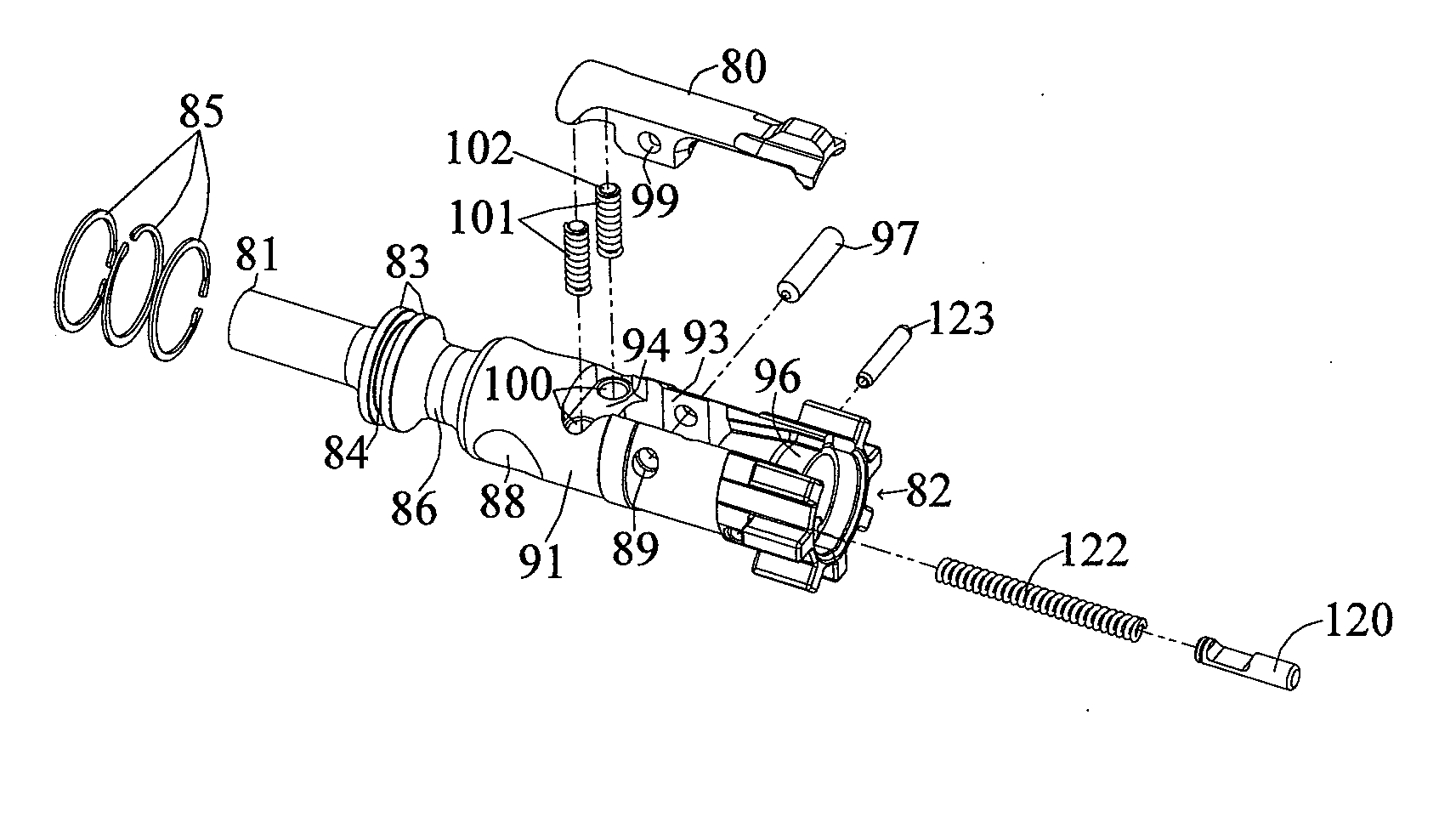
[0069]The present invention is directed towards a bolt and bolt carrier group or bolt carrier assembly for use with the M4 / M16 / AR15 family of firearms and their derivatives. As used herein, the phrases “bolt carrier assembly” and “bolt carrier group” are used interchangeably.

[0070]Unless otherwise specified, the various components which make up the trigger mechanism, upper receiver assembly, lower receiver assembly, buttstock assembly, bolt and bolt carrier assembly are those found on the prior art M4 and M16 family of firearms.

[0071]As used herein, “front” or “forward” and “distal” correspond t...


PUM


Abstract

An improved bolt and bolt carrier with integral gas key having an extension nozzle threadedly secured and pinned to the gas key for use with a direct gas operated firearm is provided. The extension nozzle is designed to receive a portion of the host firearms gas operating system. The firing pin retaining pin is oriented so as to expose its widest profile to the firing pins annular flange, increasing its service life. The bolt has a plurality of lugs extending from its forward end and an extractor recess. The extractor recess is constructed to accommodate an enlarged extractor claw while not undercutting the bolt lugs adjacent thereto. The extractor engages approximately 57% more of a seated ammunition cartridges rim as compared to some prior art AR15/M16 type extractors used with automatic firearms chambered in 6.8 SPC. The result is an improved bolt and bolt carrier which provides for increased operational reliability.

Description

[0001]This is a continuation-in-part application claiming benefit of U.S. application Ser. No. 13 / 588,294, filed Aug. 17, 2012, which claims priority under 35 U.S.C. 119(e) to U.S. provisional Ser. No. 61 / 524, 500, filed Aug. 17, 2011, each of which is herein incorporated by reference in its entirety.BACKGROUND OF THE INVENTION[0002]1. Field of the Invention[0003]The present invention relates to gas-operated firearms and, more particularly, to an improved bolt and bolt carrier for use in such firearms.[0004]2. Description of the Related Art[0005]The AR15 / M16 family of firearms and their derivatives, including all direct gas operated versions, have been in use by the military and civilian population for many years. An essential part of this firearm's design is the bolt carrier which typically includes a bolt mounted in the carrier for axial sliding movement and rotation, a firing pin slidably mounted within the bolt and bolt carrier for restricted reciprocating axial movement, and a ...

Claims


Application Information

Patent Timeline
Patent Type & Authority Applications(United States)
IPC IPC(8): F41A15/12
CPCF41A15/12F41A3/26F41A15/14F41A3/16
Inventor GOMEZ, JESUS S.
Owner LWRC INTERNATIONAL
Why Eureka
Try Eureka