Flamesheet combustor dome

Active Publication Date: 2014-04-03
H2 IP UK LTD
View PDF10 Cites 19 Cited by
  • Summary
  • Abstract
  • Description
  • Claims
  • Application Information

AI Technical Summary

Benefits of technology

[0007]The present invention discloses an apparatus and method for improving control of the fuel-air mixing prior to injection of the mixture into a combustion liner of a multi-stage combustion system. More specifically, in an embodiment of the present invention, a gas turbine combustor is provided having a generally cylindrical flow sleeve and a generally cylindrical combustion liner contained therein. The gas turbine combustor also comprises a set of main fuel injectors and a combustor dome assembly encompassing the inlet end of a combustion liner and having a generally hemispherical cross section. The dome assembly extends both axially towards the set of main fuel injectors and within the combustion

Problems solved by technology

Diffusion type nozzles historically produce relatively high emissions due to the fact that the fuel and air burn essentially upon interaction, without mixing, and stoichiometrically at high temperature to maintain adequate combustor stability and low combustion dynamics.
Air, however, can be more difficult to stage given the large quantity of air supplied by the engine compressor.
In fact, because of the general design to gas turbine combustion systems, as shown by FIG. 1, air f

Method used


Image

  • Flamesheet combustor dome
  • Flamesheet combustor dome
  • Flamesheet combustor dome

Examples


Embodiment Construction

[0018]By way of reference, this application incorporates the subject matter of U.S. Pat. Nos. 6,935,116, 6,986,254, 7,137,256, 7,237,384, 7,308,793, 7,513,115, and 7,677,025.

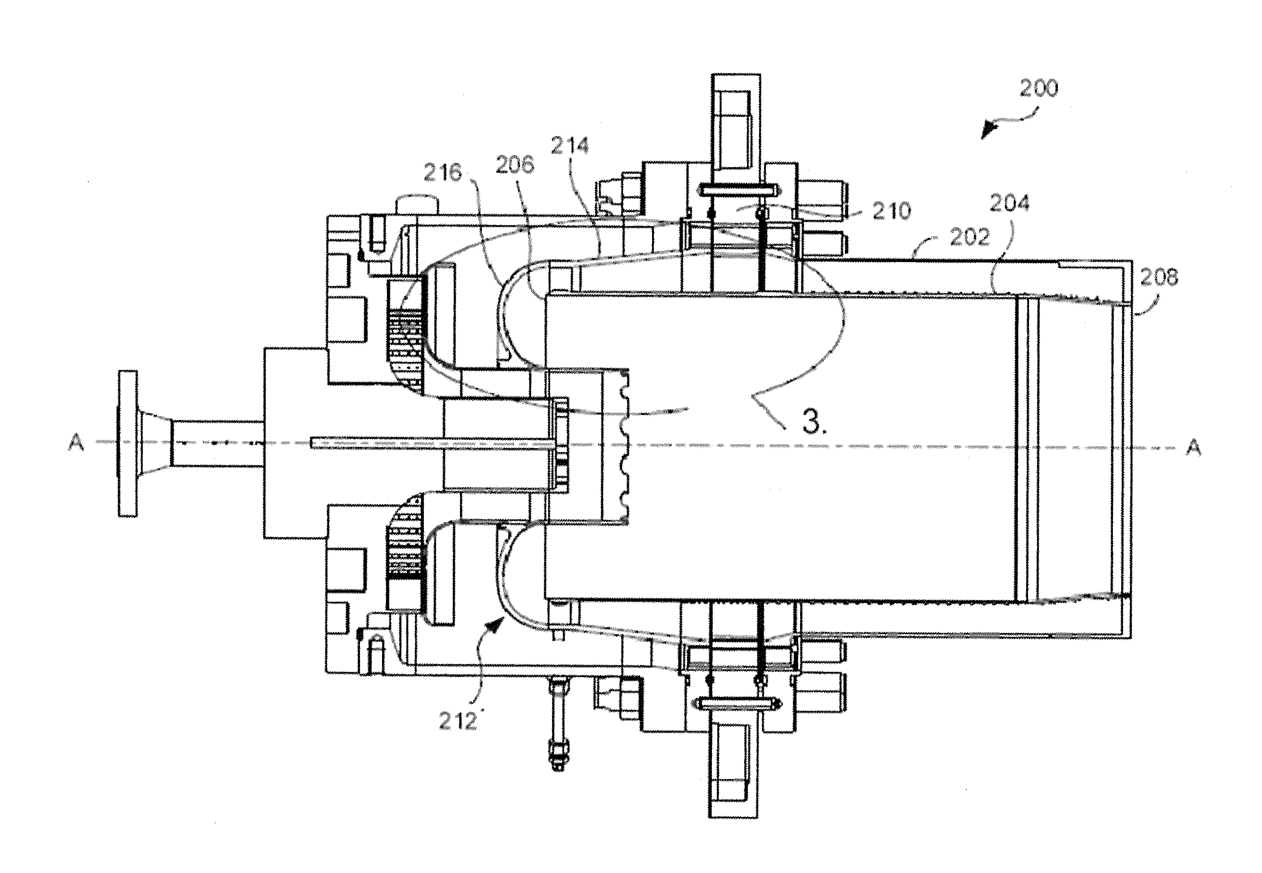
[0019]The present invention discloses a system and method for controlling velocity of a fuel-air mixture being injected into a combustion system. That is, a predetermined effective flow area is maintained through two co-axial structures forming an annulus of a known effective flow area through which a fuel-air mixture passes.

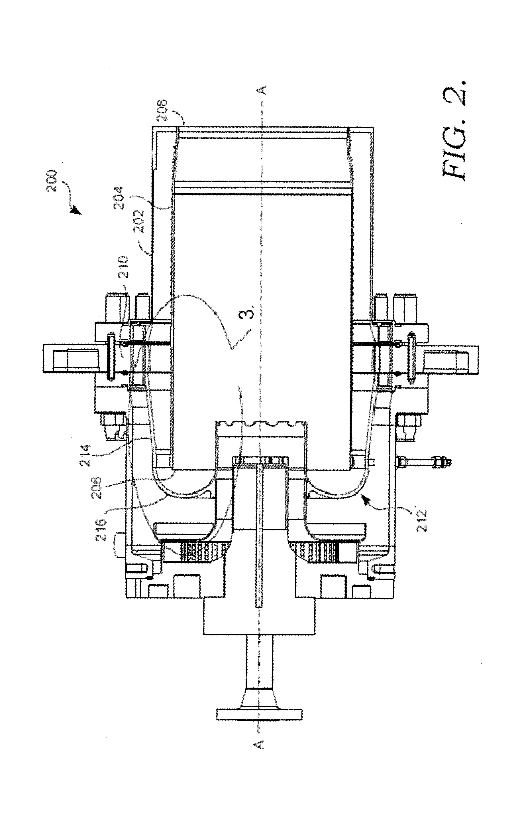
[0020]The present invention will now be discussed with respect to FIGS. 2-5. An embodiment of a gas turbine combustion system 200 in which the present invention operates is depicted in FIG. 2. The combustion system 200 is an example of a multi-stage combustion system and extends about a longitudinal axis A-A and includes a generally cylindrical flow sleeve 202 for directing a predetermined amount of compressor air along an outer surface of a generally cylindrical and co-axial combustion line...


PUM


Abstract

The present invention discloses a novel apparatus and way for controlling a velocity of a fuel-air mixture entering a gas turbine combustion system. The apparatus comprises a hemispherical dome assembly which directs a fuel-air mixture along a portion of the outer wall of a combustion liner and turns the fuel-air mixture to enter the combustion liner in a manner coaxial to the combustor axis and radially outward of a pilot fuel nozzle so as to regulate the velocity of the fuel-air mixture.

Description

CROSS-REFERENCE TO RELATED APPLICATIONS[0001]This application claims the benefit of U.S. Provisional Patent Application Ser. No. 61 / 708,323 filed on Oct. 1, 2012.TECHNICAL FIELD[0002]The present invention relates generally to an apparatus and method for directing a fuel-air mixture into a combustion system. More specifically, a hemispherical dome is positioned proximate an inlet to a combustion liner to direct the fuel-air mixture in a more effective way to better control the velocity of the fuel-air mixture entering the combustion liner.BACKGROUND OF THE INVENTION[0003]In an effort to reduce the amount of pollution emissions from gas-powered turbines, governmental agencies have enacted numerous regulations requiring reductions in the amount of oxides of nitrogen (NOx) and carbon monoxide (CO). Lower combustion emissions can often be attributed to a more efficient combustion process, with specific regard to fuel injector location, airflow rates, and mixing effectiveness.[0004]Early ...

Claims


Application Information

Patent Timeline
IPC IPC(8): F23R3/54
CPCF23R3/54F23C2201/20F23C2900/06043F23C2900/07001F23R3/14F23R3/16F23R3/286F23R3/34F23R3/343F23R2900/00014F23R2900/03343F23R3/26F23R3/60
Inventor STUTTAFORD, PETER JOHNJORGENSEN, STEPHENHUI, TIMOTHYCHEN, YANRIZKALLA, HANYOUMEJJOUD, KHALID
Owner H2 IP UK LTD
Why Eureka
Try Eureka